Reactor system including auto ignition and carbon suppression foam

a technology of carbon suppression foam and reactor system, which is applied in the direction of physical/chemical process catalysts, gas-gas reaction processes, separation processes, etc., can solve the problems of carbon formation and undesirable carbon deposits

Inactive Publication Date: 2005-07-26
GENERAL MOTORS COMPANY
View PDF11 Cites 15 Cited by
  • Summary
  • Abstract
  • Description
  • Claims
  • Application Information

AI Technical Summary

Benefits of technology

[0013]The auto-ignition and carbon-suppression foam may include a first face closest to the fuel injector and a rear fac

Problems solved by technology

f auto-ignition does occur before the mixture enters the primary reactor catalyst, these gas phase reactions will tend to f

Method used


Image

  • Reactor system including auto ignition and carbon suppression foam
  • Reactor system including auto ignition and carbon suppression foam
  • Reactor system including auto ignition and carbon suppression foam

Examples


Embodiment Construction

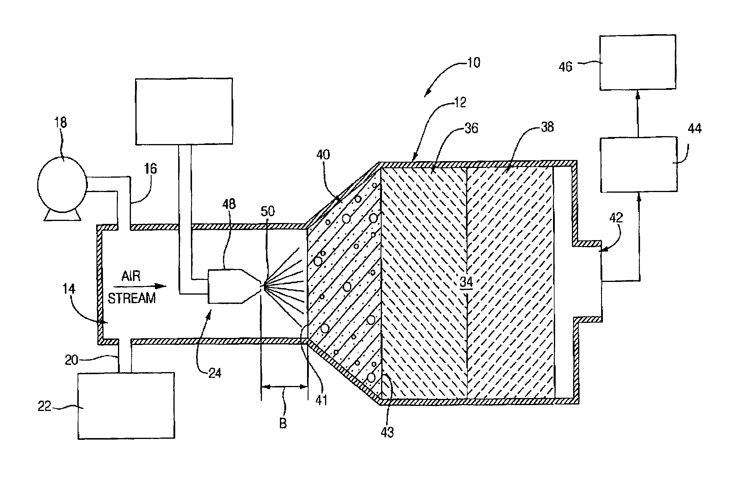
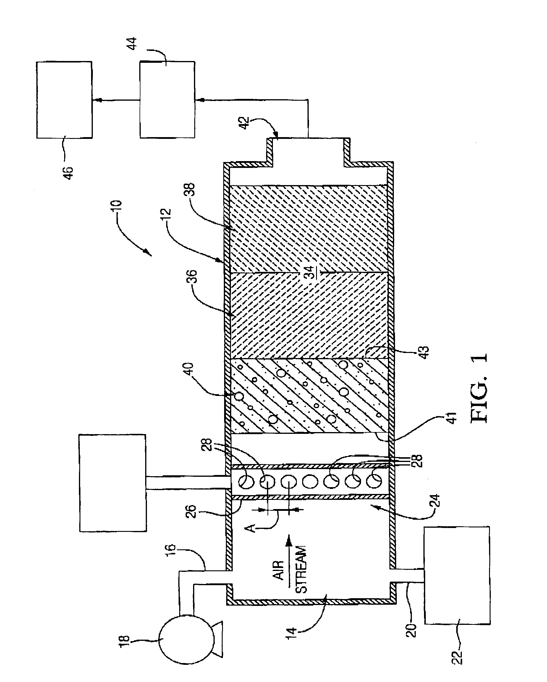
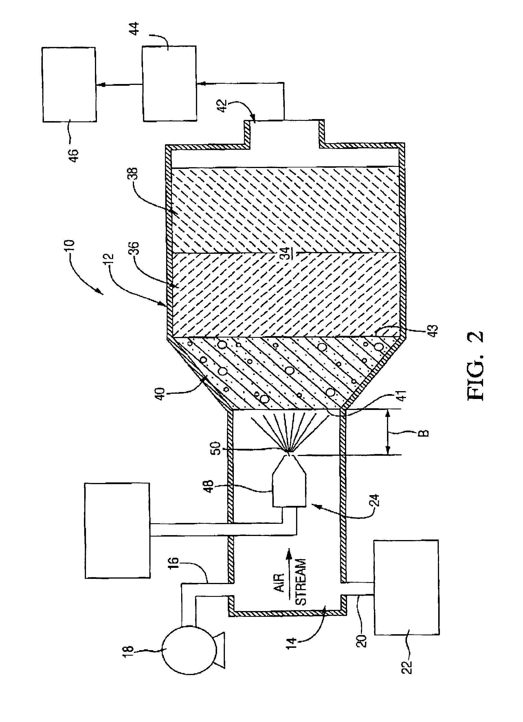
[0020]FIG. 1 illustrates a fuel cell system including a reactor system according to the present invention. The embodiment of FIG. 1 is particularly suited for use with gaseous or vaporized fuel. A reactor 10 is provided and includes a housing 12 which typically would be generally tubular in shape and includes an inlet portion 14. The inlet portion 14 is generally an open chamber into which air is charged via an air line 16 which typically is connected to a compressor or pump 18. Likewise, steam is charged into the inlet portion using the steam charge line 20 that is connected to a steam generator or boiler 22. A fuel injector 24 is provided downstream of the inlet portion 14 and is constructed and arranged to charge a carbon-based fuel into the flow path of the air in stream travelling through the reactor 10. The fuel injector 24 shown in FIG. 1 includes at least one tube 26 traversing the inlet cross section and includes a plurality of holes 28 formed therein for injecting fuel int...


PUM

PropertyMeasurementUnit
Fractionaaaaaaaaaa
Fractionaaaaaaaaaa
Pore sizeaaaaaaaaaa

Abstract

A reactor system including a reactor housing having an inlet portion defined at one end of the housing and having a discharge opening formed in the housing at an opposite end. An air intake charge line is connected to the housing for charging air into the inlet portion. A steam charge line is connected to the housing for charging steam into the inlet portion. A fuel injector is positioned in the housing for injecting fuel into the stream of air and steam flowing through the housing. A fuel charge line is connected to the fuel injector for charging a carbon-based fuel into the injector. A catalyst bed is carried in the housing and positioned downstream of the fuel injector and at least a portion of the catalyst bed includes a catalyst for promoting the reformation of the carbon-based fuel to produce hydrogen. An auto-ignition suppression and carbon-suppression foam is carried in the housing and positioned between the catalyst bed and the fuel injector.

Description

TECHNICAL FIELD[0001]This invention relates to a reactor system for producing hydrogen for use in a fuel cell, and more particularly to a reactor system including an auto ignition and carbon suppression foam.BACKGROUND OF THE INVENTION[0002]A fuel cell is an electrochemical device for continuously converting chemicals—a fuel and an oxidant—into direct-current electricity. It consists of two electronic-conductor electrodes separated by an ion-conducting electrolyte with provision for the continuous movement of fuel, oxidant and reaction product into and out of the cell. Fuel cells differ from batteries in that electricity is produced from chemical fuels fed to them as needed, so that their operating life is theoretically unlimited. Fuel is oxidized at the anode (negative electrode), giving electrons to an external circuit. Simultaneously with the electron transfer, an ionic current in the electrolyte completes the circuit. The fuels range from hydrogen and carbonaceous materials to r...

Claims


Application Information

Patent Timeline
IPC IPC(8): B01J19/26B01J19/24B01J12/00C01B3/00C01B3/38B01J8/04C01B3/36C01B3/40H01M8/06H01M8/10
CPCB01J8/043B01J8/0492B01J12/007B01J19/2485B01J19/26C01B3/382H01M8/0612H01M8/0631B01J2208/025B01J2219/0025B01J2219/00263B01J2219/182B01J2219/185C01B2203/00C01B2203/0244C01B2203/0288C01B2203/044C01B2203/049C01B2203/066C01B2203/0844C01B2203/1011C01B2203/1023C01B2203/1052C01B2203/1064C01B2203/107C01B2203/1276C01B2203/1288C01B2203/142C01B2203/82Y02E60/50
Inventor GOEBEL, STEVEN G.VOECKS, GERALD E.CARTER, ROBERT N.
Owner GENERAL MOTORS COMPANY
Why Eureka
Try Eureka