Optical multiplex short coherence interferometry on the eye

a coherence interferometry and optical multiplex technology, applied in the field of eye internal geometry detection and imaging, can solve the problems of difficult use of subjective methods, limited access to the eye geometric structure, and difficulty in detecting aberrations in the ey

Inactive Publication Date: 2005-07-26
CARL ZEISS MEDITEC AG
View PDF1 Cites 27 Cited by
  • Summary
  • Abstract
  • Description
  • Claims
  • Application Information

AI Technical Summary

Benefits of technology

[0011]This object is met in that the short coherence interferometric depth scan is carried out by changing the optical length of the interferometer measurement arm and the interferometer light source is imaged in the primary measurement image in the eye via an intermediate image by means of optics whose focal length corresponds approximately to the optical length of the schematic eye.

Problems solved by technology

Subjective methods are rarely used due to the required cooperation of the test subject for rigorous clarification of clinical questions.
Also, the previously known objective methods for detecting aberrations in the eye allow only limited access to the geometric structure of the eye because they only show the total effect of all optically active structures of the eye and can not clearly separate the influences of individual components.
The described short coherence interferometry has the disadvantage that many individual transversely adjacent depth scans must be carried out along individual measurement beams one after the other in a time-consuming manner to obtain topograms or tomograms.
In particular, the use of a method of this type on patients is problematic.

Method used


Image

  • Optical multiplex short coherence interferometry on the eye
  • Optical multiplex short coherence interferometry on the eye
  • Optical multiplex short coherence interferometry on the eye

Examples


Embodiment Construction

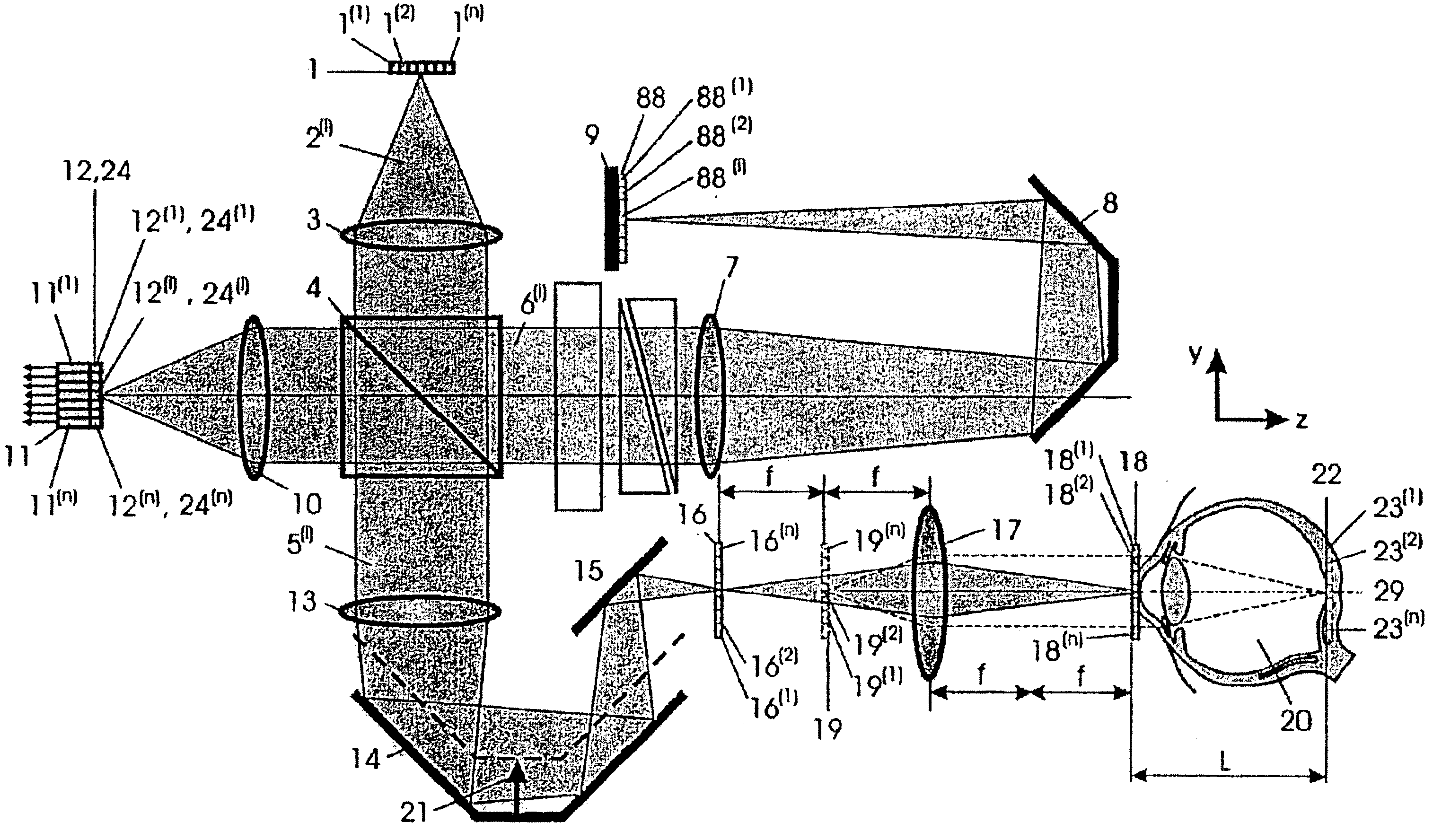
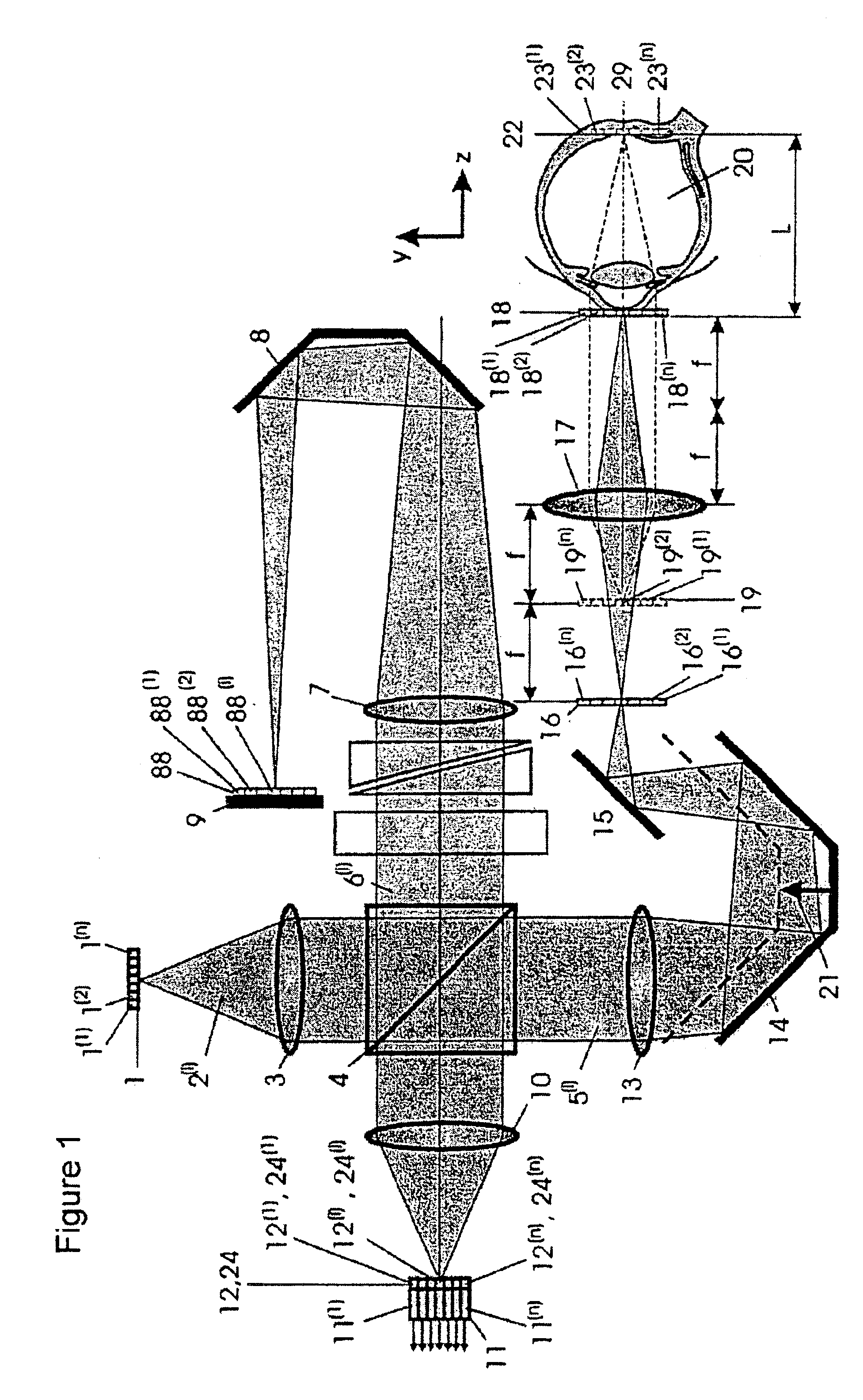
[0019]By “short coherence” is meant that light of short coherence length is used in this interferometry method. In this connection, the optical path length of the measurement beam of a two-beam interferometer is scanned by matching or tuning the length of the reference beam after interference occurs. During this depth scan, as it is called, the reference mirror is moved along the axis of the reference beam. When the path length of the reference beam from the beam splitter to the measurement location and back within the coherence length is equal to the path length of the measurement beam from the beam splitter to a light-reemitting point in the object (eye) and back to the beam splitter, interference occurs at the interferometer output. The area at the measurement location contributing to this interference is called the “coherence window”. By continuously displacing the reference mirror, the z-position of light-reemitting points in the object is recorded by means of the interference ...


PUM


Abstract

The invention is directed to the detection and imaging of the internal geometry of the eye, particularly of the important components for imaging in the eye such as the cornea, lens, vitreous body and retinal surface, by multichannel short coherence interferometry. A method and arrangement for obtaining topograms and tomograms of the eye structure by many simultaneously recorded interferometric depth scans through transversely adjacent points in the pupil using spatially coherent or spatially partially coherent light sources. The depth scan is carried out by changing the optical length of the interferometer measurement arm by means of a retroreflector. By continuously displacing the retroreflector, the z-position of the light-reemitting point in the eye can be determined by means of the occurring interference. It is possible to record depth scans simultaneously through the use of spatially coherent or spatially partially coherent light beams comprising a plurality of partial beams.

Description

CROSS-REFERENCE TO RELATED APPLICATIONS[0001]This application claims priority of German Application No. 101 42 001.3, filed Aug. 28, 2001, the complete disclosure of which is hereby incorporated by reference.BACKGROUND OF THE INVENTION[0002]a) Field of the Invention[0003]The present invention is directed to the detection and imaging of the internal geometry of the eye, particularly of the important components for imaging in the eye such as the cornea, lens, vitreous body and retinal surface, by means of multiplex multichannel short coherence interferometry.[0004]b) Description of the Related Art[0005]Owing to new developments in ophthalmology characterized by many different types of operative procedures on the eye lens (e.g., cataract surgery) and on the cornea (refractive cornea surgery), there is a considerable demand for measurement methods which show the optically active geometry of the eye quantitatively. One task in this connection is the measurement of the imaging quality of ...

Claims


Application Information

Patent Timeline
Patent Type & Authority Patents(United States)
IPC IPC(8): A61B3/10G01B9/02A61B3/12A61B3/117A61B3/103
CPCA61B3/102G01B9/02027G01B9/02002G01B9/02091G01B9/02058G01B9/02063A61B3/103A61B3/1173A61B3/12G01B2290/15G01B2290/45
Inventor FERCHER, ADOLF FRIEDRICH
Owner CARL ZEISS MEDITEC AG
Why Eureka
Try Eureka