System and method for monitoring defects in structures

a technology of system and method, applied in the direction of mechanical measurement arrangement, mechanical roughness/irregularity measurement, instruments, etc., can solve the problem of greater potential drop, and achieve the effect of increasing electrical resistance and greater potential drop

Inactive Publication Date: 2005-07-26
GENERAL ELECTRIC CO
View PDF6 Cites 35 Cited by
  • Summary
  • Abstract
  • Description
  • Claims
  • Application Information

AI Technical Summary

Benefits of technology

[0006]A system and method for monitoring defects in a structure are provided. This invention makes use of an electrical current flowing through the material of the structure, e.g., a pipe or thin walled vessel, and a set of electrodes or leads attached to the outside of the pipe or vessel and an appropriate reference to measure the potential (voltage) drop between the attached electrodes. The measured potential drop between the attached electrodes will increase as a result of corrosion. As the thickness of the pipe or vessel wall is reduced due to corrosion, the electrical resistance will increase causing a greater potential drop. Use of an appropriate reference sample will allow this measurement to be taken accurately without variation caused by thermocouple effects, power-line noise interference, offset and gain drift of electronic components or other effects that typically cause noise when measuring small potential differences.

Problems solved by technology

As the thickness of the pipe or vessel wall is reduced due to corrosion, the electrical resistance will increase causing a greater potential drop.

Method used


Image

  • System and method for monitoring defects in structures
  • System and method for monitoring defects in structures
  • System and method for monitoring defects in structures

Examples


Embodiment Construction

[0013]Preferred embodiments of the present invention will be described hereinbelow with reference to the accompanying drawings. In the following description, well-known functions or constructions are not described in detail to avoid obscuring the invention in unnecessary detail.

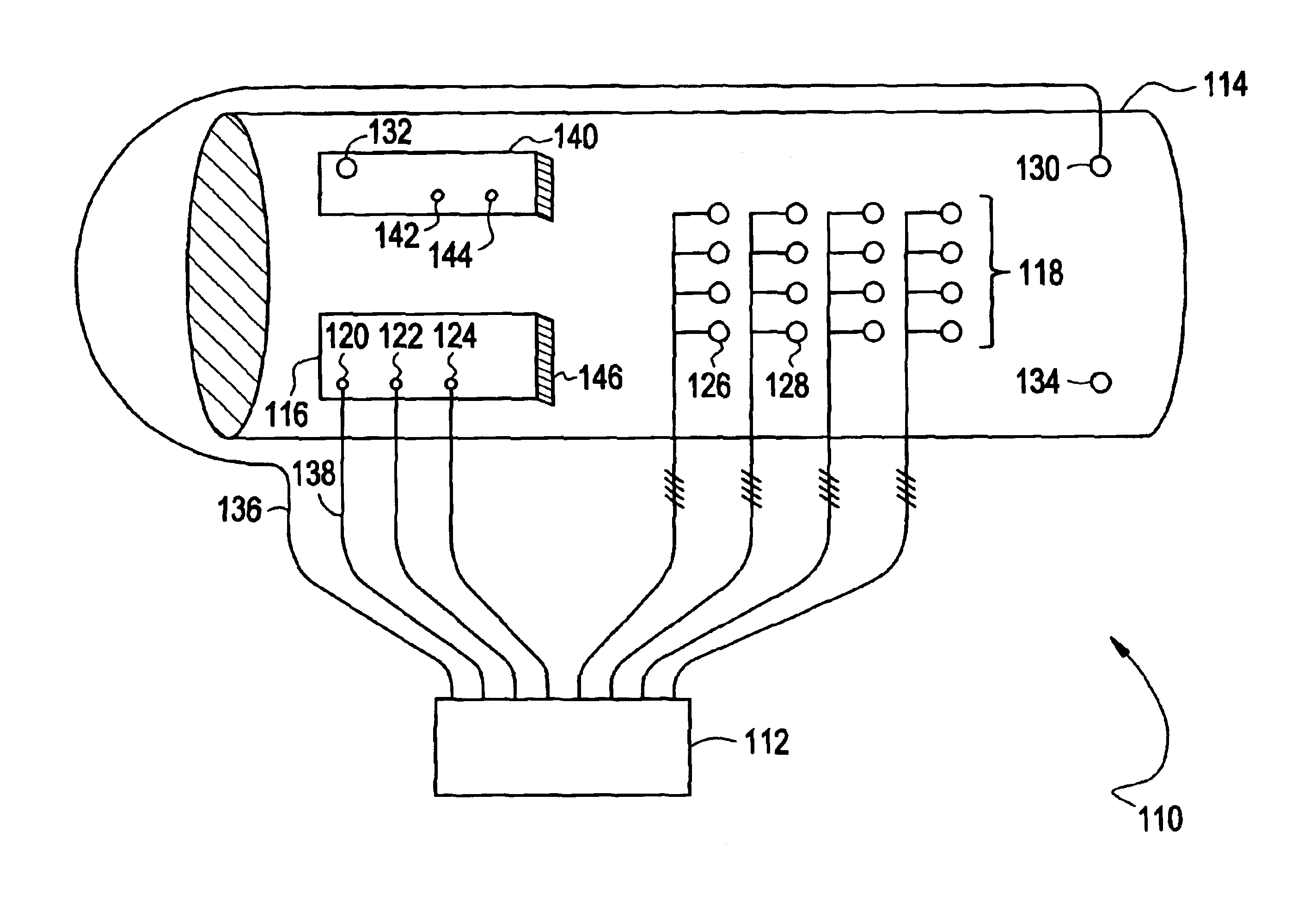
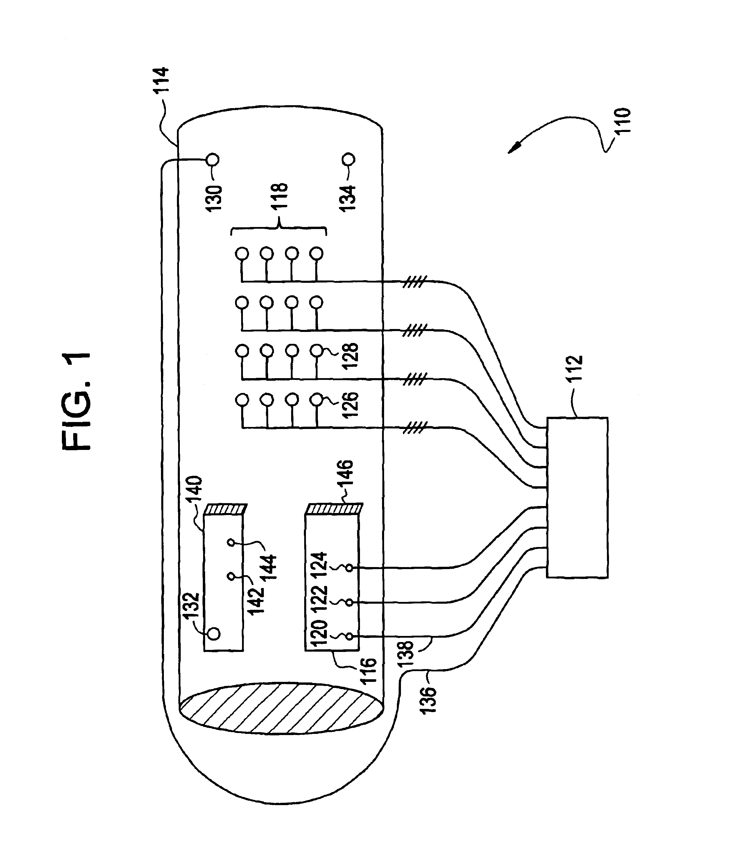
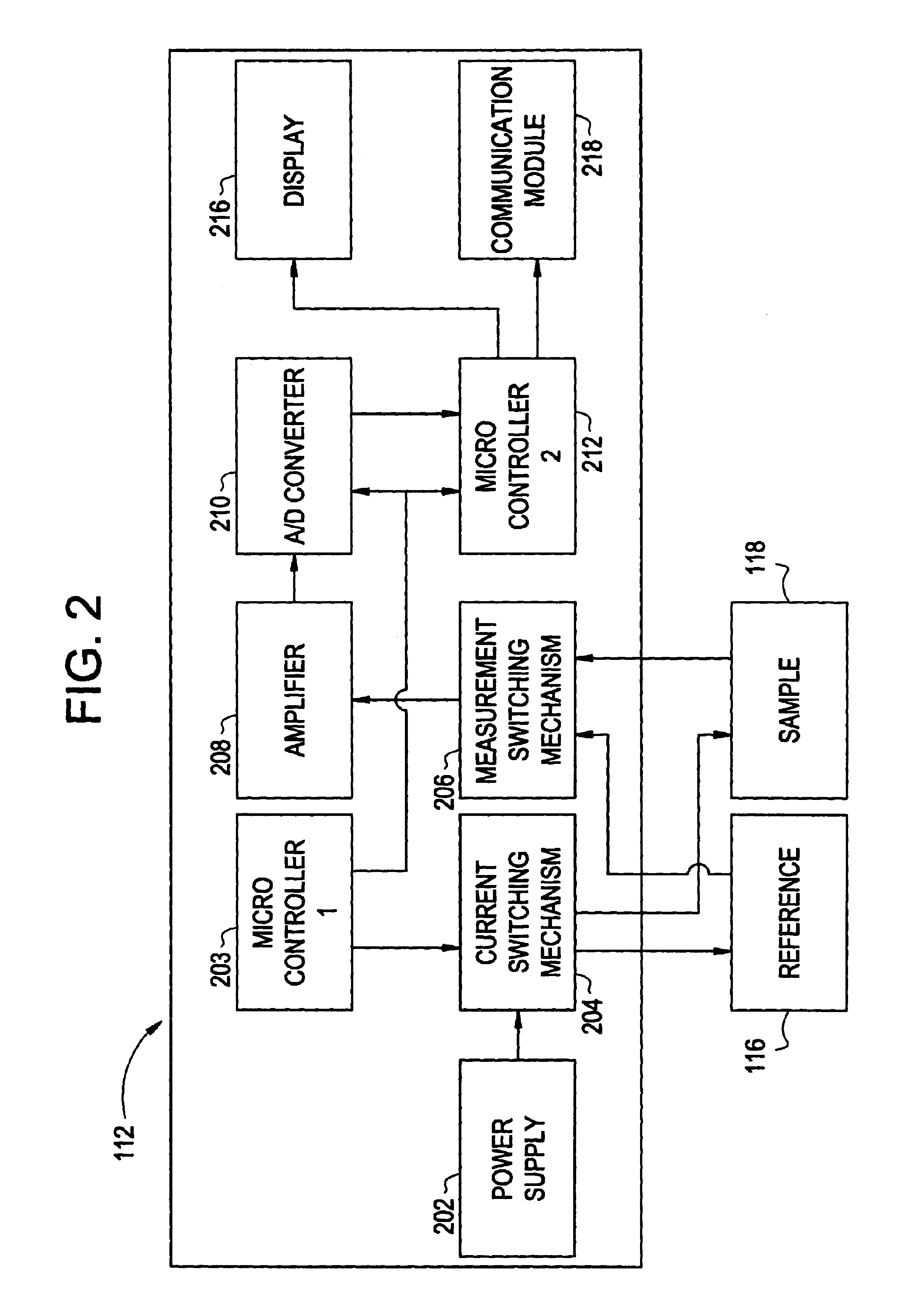
[0014]A system and method to monitor defects in a structure, e.g., a pipe or vessel, and to directly determine and quantify the amount of remaining wall thickness of the structure are provided. The invention will monitor a predetermined area, e.g., a monitoring area, of a sample and determine the remaining thickness of the sample in the area. This data can then be used to determine the safety of plant operations based on comparison of the remaining wall thickness to the design limits of the sample determined through engineering means. The invention is suited for monitoring a pipe or vessel operating between, but not limited to, −40 F. to 1000 F. By injecting large drive currents, e.g., up to 1000 Amps, and si...


PUM

PropertyMeasurementUnit
thicknessaaaaaaaaaa
structureaaaaaaaaaa
currentaaaaaaaaaa

Abstract

A system and method for monitoring defects in a structure are provided. The system includes a power supply for supplying an electric current to a monitoring area of the structure and a reference; a measurement circuit for measuring a potential drop across at least two contact points of the monitoring area and at least two contact points of the reference; and a processor adapted to determine a ratio of the monitoring area potential drop to the reference potential drop indicative of a percentage change in a thickness of the structure. The method includes the steps of supplying the current to the monitoring area and the reference; measuring a first potential drop across the monitoring area and the reference; and determining the ratio indicative of the percentage change in the thickness of the structure.

Description

BACKGROUND OF THE INVENTION[0001]This disclosure relates generally to systems and methods for monitoring of structures, and more particularly, to systems and methods for continuously monitoring structures, e.g., pipes and vessels, for defects such as wall thinning caused by corrosion.[0002]The petroleum and chemical industry has been searching for a means to monitor the condition of piping and vessels in facilities used for a variety of product flow and product processing. During the normal operation of these facilities, corrosion and erosion occur as a result of various products flowing through pipes and vessels and lead to a thinning of the pipes' and vessels' walls. The result of this wall thinning can range from loss of production, due to pipe leaks, to catastrophic failures which present safety and property damage issues. The operating conditions of the piping and vessels ranges from ambient temperatures of the surrounding environment (−40 F to 120 F) to very elevated temperatu...

Claims


Application Information

Patent Timeline
Patent Type & Authority Patents(United States)
IPC IPC(8): G01B7/06G01B5/28G01N27/20G01B7/02G01B7/28
CPCG01B7/281G01B7/02G01B7/06G01N27/20
Inventor BATZINGER, THOMASMAY, ANDREWALLISON, PETERLESTER, CARL
Owner GENERAL ELECTRIC CO
Why Eureka
Try Eureka