
Process for initializing and updating the topology of a high-voltage or medium-voltage electrical power station

a technology of electrical power station and topology, applied in symbolic schematics, instruments, cad techniques, etc., can solve the problems of time-consuming and laborious operation of operators, and the inability of conventional systems to identify all possible schematics or all their particular features, so as to simplify the operation. the effect of task

Inactive Publication Date: 2005-07-26
ALSTOM SA
View PDF10 Cites 7 Cited by
  • Summary
  • Abstract
  • Description
  • Claims
  • Application Information

AI Technical Summary

Benefits of technology

"The present invention proposes optimizing the operation of a digital busbar-protection system in a power station by using a basic schematic and a topology program to automatically recognize the components of the system and their connections. The system uses a combination of topological compilation and graph processing algorithms to quickly and accurately identify the components and their connections. The system also allows the operator to enter a second topological level of assignment for the components, further simplifying the process. The invention aims to make the operation of the protection system more efficient and user-friendly."

Problems solved by technology

Thus these conventional systems cannot identify all possible schematics or all their particular features, because the characteristics of the actual schematic must necessarily have been catalogued in order to be retrieved.
Also, the operator's task is then time-consuming because the operator must recognize if the basic schematic of the network is one of the catalogued schematics available to him.

Method used


Image

  • Process for initializing and updating the topology of a high-voltage or medium-voltage electrical power station
  • Process for initializing and updating the topology of a high-voltage or medium-voltage electrical power station
  • Process for initializing and updating the topology of a high-voltage or medium-voltage electrical power station

Examples


Embodiment Construction

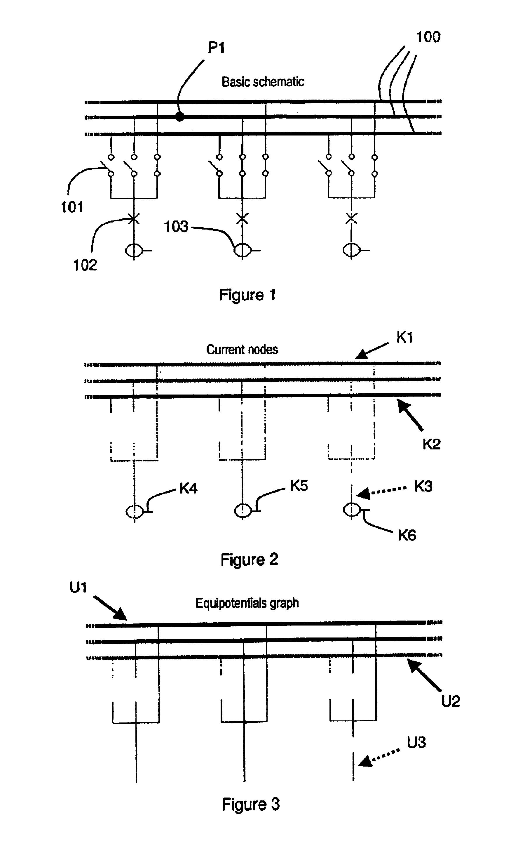
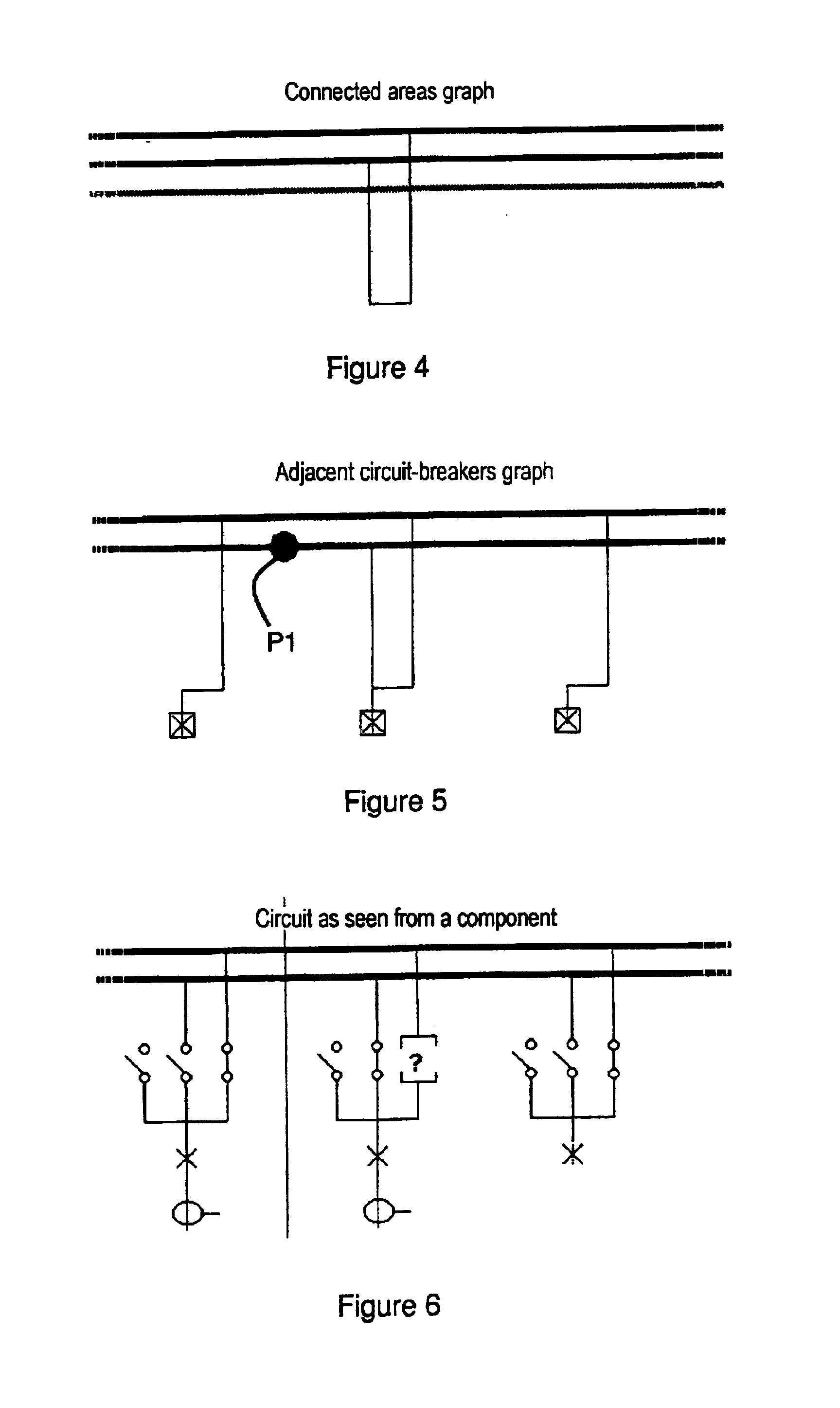
[0040]FIG. 1 shows the basic schematic of one example of an electrical circuit of a power station with three sets of busbars 100. In other words, the power station defines three zones as shown in FIG. 7. The power station includes nine disconnectors 101, three circuit-breakers 102 and three current transformers 103. Five disconnectors and one circuit-breaker are open. The point P1 represents any point of the circuit, and serves as a reference for the adjacent circuit-breakers graph in FIG. 6.

[0041]In FIG. 2, the graph of the current nodes of the circuit includes six nodes K1 to K6. The nodes K4 to K6 are the secondary windings of the current transformers. The node K3 is a conductor isolated from the remainder of the circuit by an open circuit-breaker. The node K1 is the most extensive because it includes two sets of busbars that are interconnected.

[0042]In FIG. 3, the equipotentials graph includes three equipotentials U1, U2 and U3 that correspond to the nodes K1 to K3 in FIG. 2. It...


PUM


Abstract

The process is intended to optimize the operation of a digital protection system for protecting sets of busbars in the power station and uses a basic schematic of the electrical configuration of the power station obtained from information on the type of components used in the power station, and on the possible connections and accesses to said components. The information is assigned to management units of the digital protection system, said management units comprising peripheral measurement units and at least one centralization unit. A topological compilation process is implemented to provide a compiled schematic topology, and to provide a compiled assignment topology of the components in the power station and of their connections to the management units. A partial graph, whose structure depends on the type of information searched for and the status of each component of the power station, is obtained for each peripheral unit. A complete graph is then computed in one or more centralization units by algorithms which superpose partial graphs.

Description

[0001]The invention relates to a process for initializing and updating topology, the process being intended to optimize the operation of a digital protection system for protecting sets of busbars in a high-voltage or medium-voltage electrical power station. The protection system is intended primarily to detect short circuits in a set of busbars and to detect failure of a component of the network such as a disconnector, a circuit-breaker, a transformer or any other component in the overall schematic of the set of busbars. It is further intended to validate commands affecting the status of the components, for example.BACKGROUND OF THE INVENTION[0002]Generally speaking, a digital busbar-protection system requires as input information a basic schematic corresponding to the configuration of the set of busbars in the electrical power station that are managed by the system. Recognizing the basic schematic obviously requires a knowledge of the components of the network and information to be...

Claims


Application Information

Patent Timeline
Patent Type & Authority Patents(United States)
IPC IPC(8): G06F17/50H02J3/00
CPCG06F17/5004G06F17/509G06F2217/74G06F2217/78H02J3/00H02J2003/007Y04S10/545Y04S40/22Y02E40/76Y02E60/76G06F30/18G06F30/13G06F2111/12G06F2119/06H02J2203/20Y02E40/70Y02E60/00Y04S10/50Y04S40/20
Inventor CARRILLO, JEAN-JACQUES
Owner ALSTOM SA
Learn More