Device which follows the position of the sun

a technology of tracking device and sun ray, applied in the field of diffractively, can solve the problems of large and expensive tracking device, large and expensive optical apparatus, and the above-described disadvantages of tracking, and achieve the effect of simple structure and efficient light conversion

Inactive Publication Date: 2005-08-02
LEONHARD KURZ STIFTUNG & CO KG
View PDF13 Cites 17 Cited by
  • Summary
  • Abstract
  • Description
  • Claims
  • Application Information

AI Technical Summary

Benefits of technology

[0008]The object of the invention is to provide an optical apparatus of the kind set forth in the opening part of this specification, which is of a simple structure and affords the respectively desired light deflection and / or light concentration effect. The optical apparatus provides particularly efficient conversion of light for uses in solar installations.

Problems solved by technology

This requires large and expensive tracking devices, which precisely control the position of these generally bulky and heavy optical apparatuses.
However, the sun ray concentrator consisting of prisms suffers from the above-described disadvantages in terms of tracking.
In addition, because of the prisms, shadow effects occur which reduce the conversion rate.
In addition, this arrangement involves irregular distribution of energy at the surface of the receiver.

Method used


Image

  • Device which follows the position of the sun
  • Device which follows the position of the sun
  • Device which follows the position of the sun

Examples


Embodiment Construction

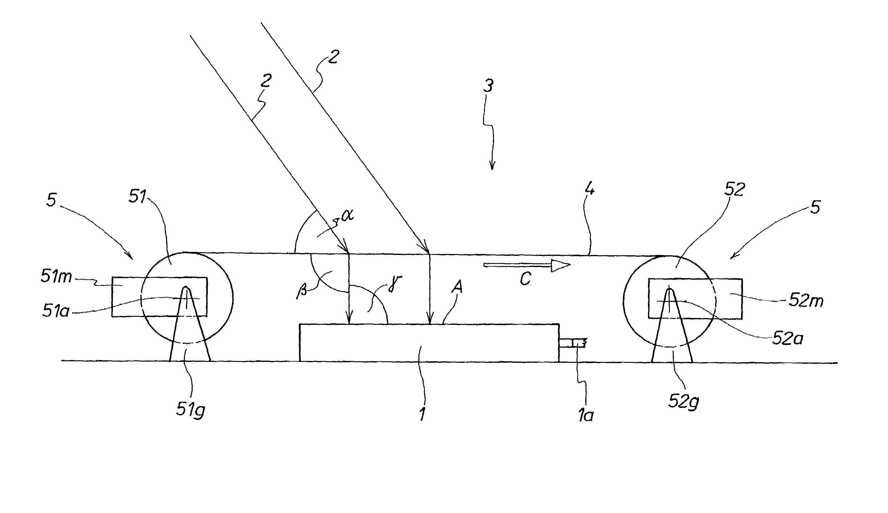
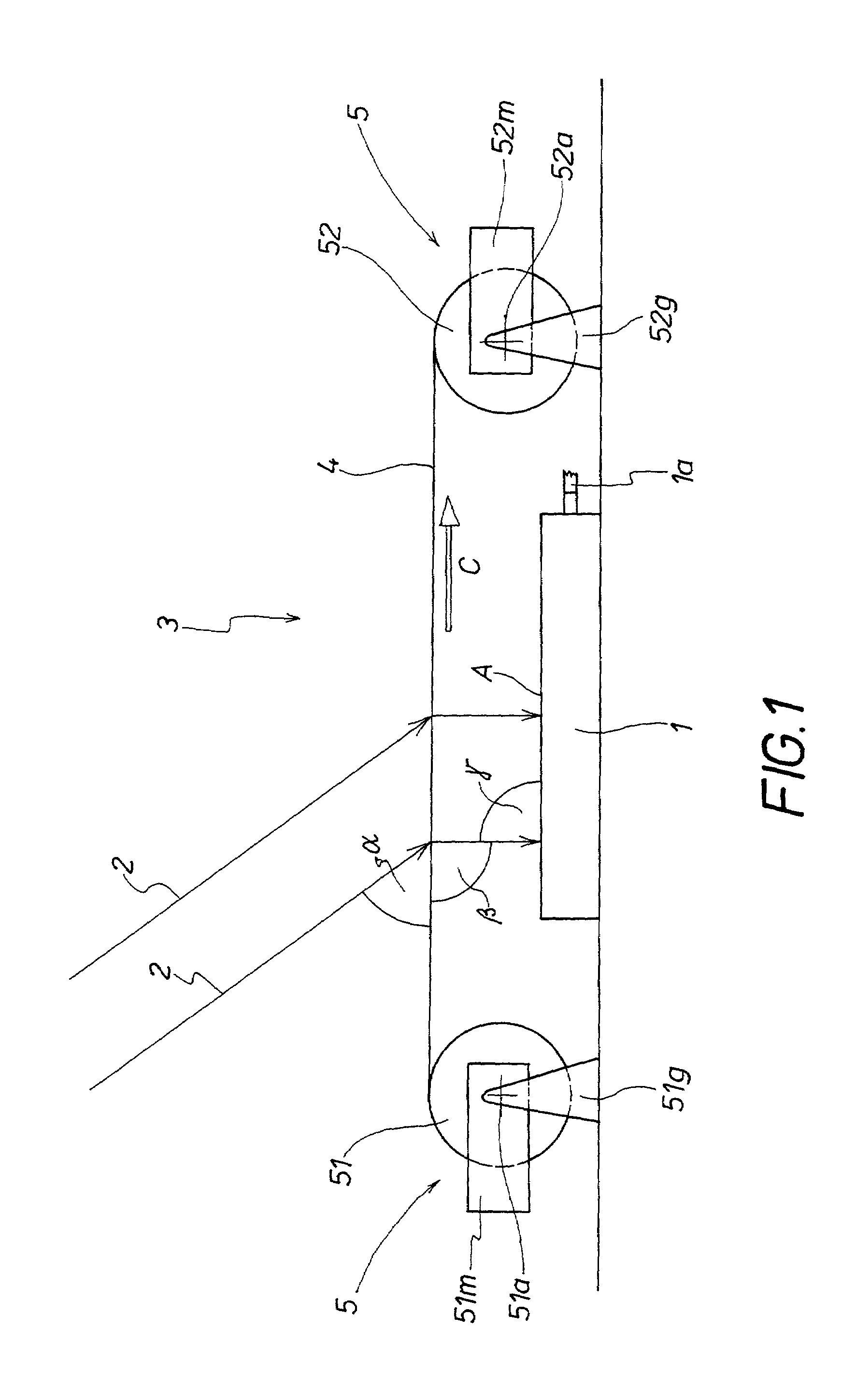
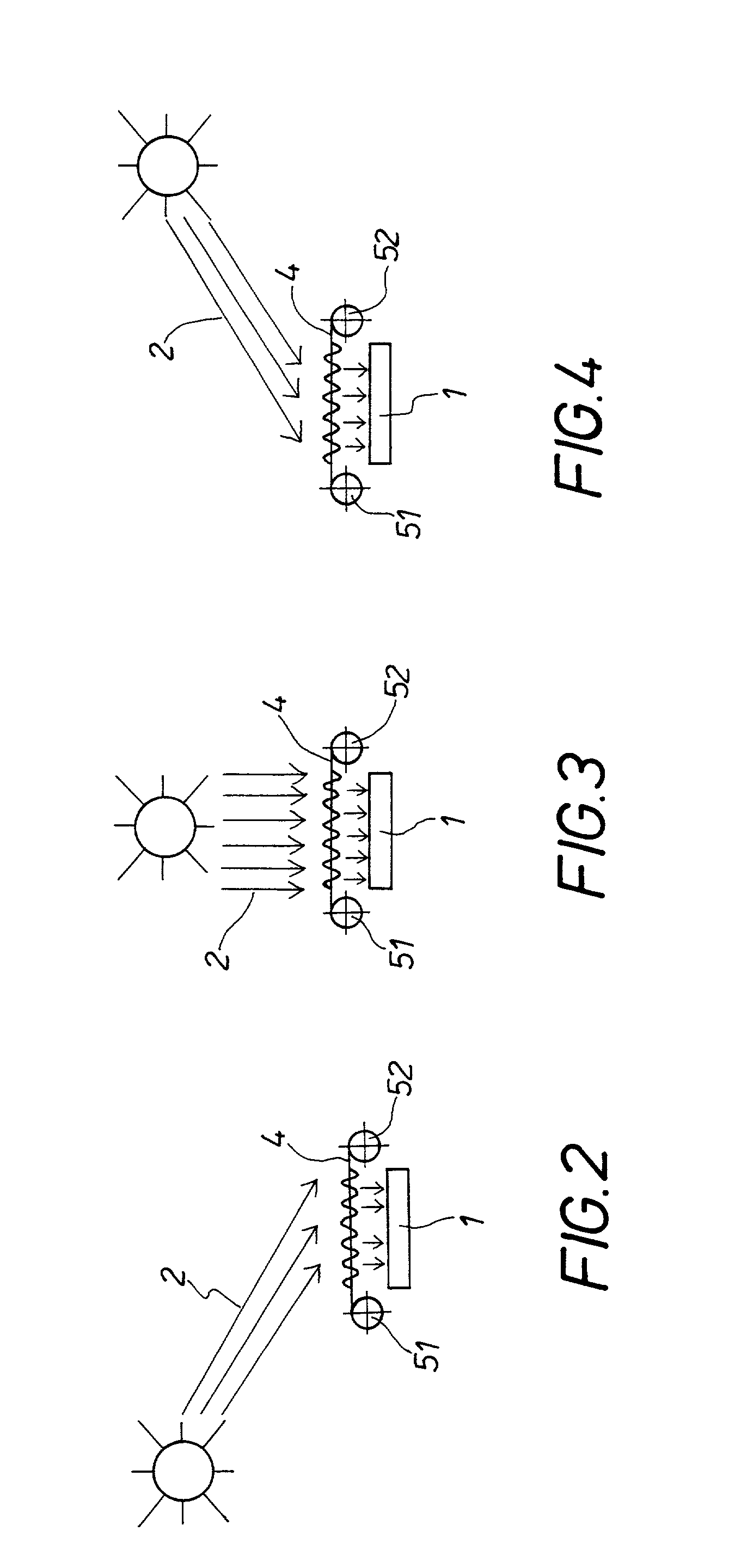
[0033]The solar installation in FIG. 1 has a solar element 1. The solar element 1 can be an individual solar element or it can be a battery of solar elements arranged in mutually juxtaposed relationship. The solar element 1 can be in the form of a photovoltaic solar cell or a heat-generating solar collector. The sunlight 2 which is irradiated on to the solar element 1 is converted by the solar element 1 into electrical or heat energy. The energy produced is fed at the output 1a of the solar element into a network (not shown) or an energy storage arrangement.

[0034]Associated with the solar element 1 is an optical apparatus 3 which passes the sunlight 2, which is incident at the angle α in dependence on the position of the sun, on to the surface of the solar element 1. The optical apparatus 3 directs the sunlight 2 on to the surface of the solar element 1 at an angle as perpendicular to the surface of the solar element 1 as possible in each case, in order to make the most efficient po...


PUM


Abstract

A solar installation is described. It has a solar element and a diffractively and/or refractively operating optical apparatus by way of which the incident sunlight is passed directedly perpendicularly on to the solar element. The optical apparatus is caused to track the position of the sun by way of a tracking device.
The optical apparatus uses a light-deflecting foil having portions of different natures with a structure having a different optical action. By virtue of the action of the tracking device the holographic foil is moved relative to the solar element so that different portions of the foil move into an operative position above the solar element in succession during the tracking procedure.

Description

[0001]This application claims priority based on an International Application filed under the Patent Cooperation Treaty, PCT / DE00 / 01778, filed on May 26, 2000, and German Application No. 199 24 783.8, filed on May 29, 1999.BACKGROUND OF THE INVENTION[0002]The invention concerns a diffractively and / or refractively operating optical apparatus for passing incident light, preferably sunlight, on to a receiver, preferably on to a solar element. The optical apparatus includes a tracking device which is controlled based on the variation with respect to time of the relative position of the light source and the receiver, preferably based on the position of the sun.[0003]Optical apparatuses that track the direction of sunlight are used in solar installations. They are associated with the solar elements, to make the most efficient possible use of the sunlight; in order to direct the incident sunlight on to the solar element on an angle as close to perpendicular as possible. In the practical con...

Claims


Application Information

Patent Timeline
Patent Type & Authority Patents(United States)
IPC IPC(8): F24J2/08F24J2/06F24J2/38G02B5/18G05D3/10G01C1/00F24S23/00F24S23/30F24S50/20G01J1/02G01S3/786G02B5/32G02B26/08H01L31/042H01L31/052
CPCF21S11/00F24J2/06F24J2/085F24J2/38G02B5/1828G05D3/105Y02E10/43Y02E10/44Y02E10/47Y02E10/52F24S23/00F24S23/31F24S50/20
Inventor KURZ, WALTER
Owner LEONHARD KURZ STIFTUNG & CO KG
Why Eureka
Try Eureka