Casting method and apparatus

Inactive Publication Date: 2005-08-02
INT TRUCK INTPROP LLC
View PDF3 Cites 4 Cited by
  • Summary
  • Abstract
  • Description
  • Claims
  • Application Information

AI Technical Summary

Benefits of technology

[0014]In the invention, the use of green sand is eliminated by replacing the green sand molds with mold elements formed from green sand for combination with core elements that are formed by core sand and by using reusable mold-core assembly carriers that return the mold-core assemblies together and intact as they

Problems solved by technology

The structural integrity of the green sand molds, however, is not completely satisfactory and the green sand can easily yield to the pressure that may be exerted by the hands of a workman.
This method entails substantial labor costs and opportunities for unreliable castings.
This manufacturing method provides an opportunity for the green sand of the mold to be deformed by a workman in assembly of the core elements within the green sand mold, and an opportunity for a lack of reliability in maintaining a reliable location of the plurality of core elements one to the other.
The result is that there is no assurance that the thickness of the internal walls of the cylinder head will be reliably maintained during the manufacture, and there

Method used


Image

  • Casting method and apparatus
  • Casting method and apparatus
  • Casting method and apparatus

Examples


Embodiment Construction

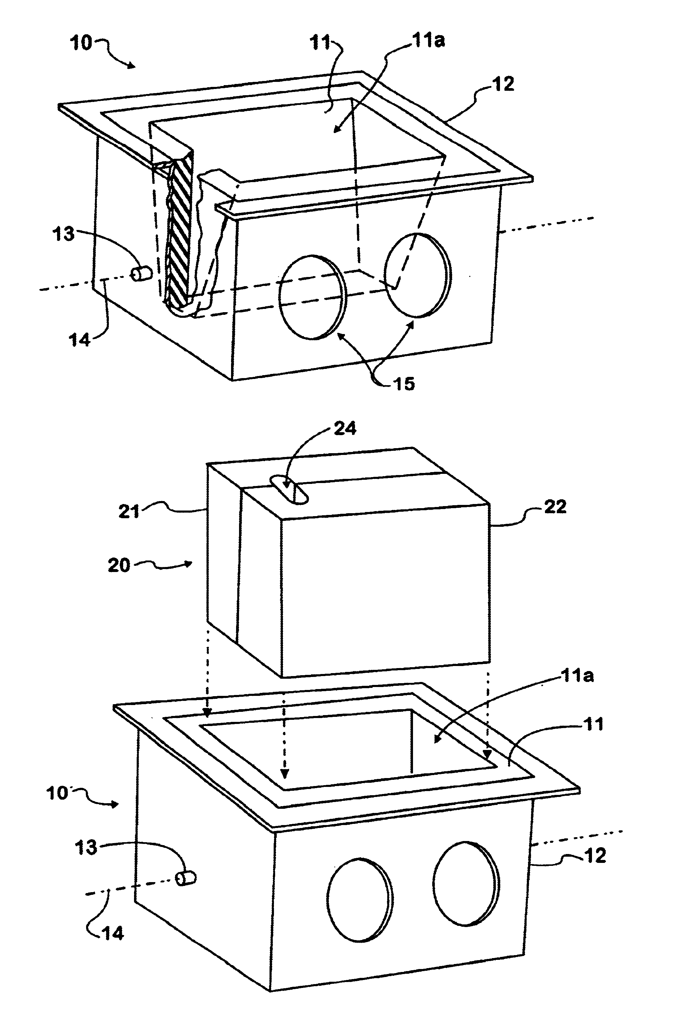
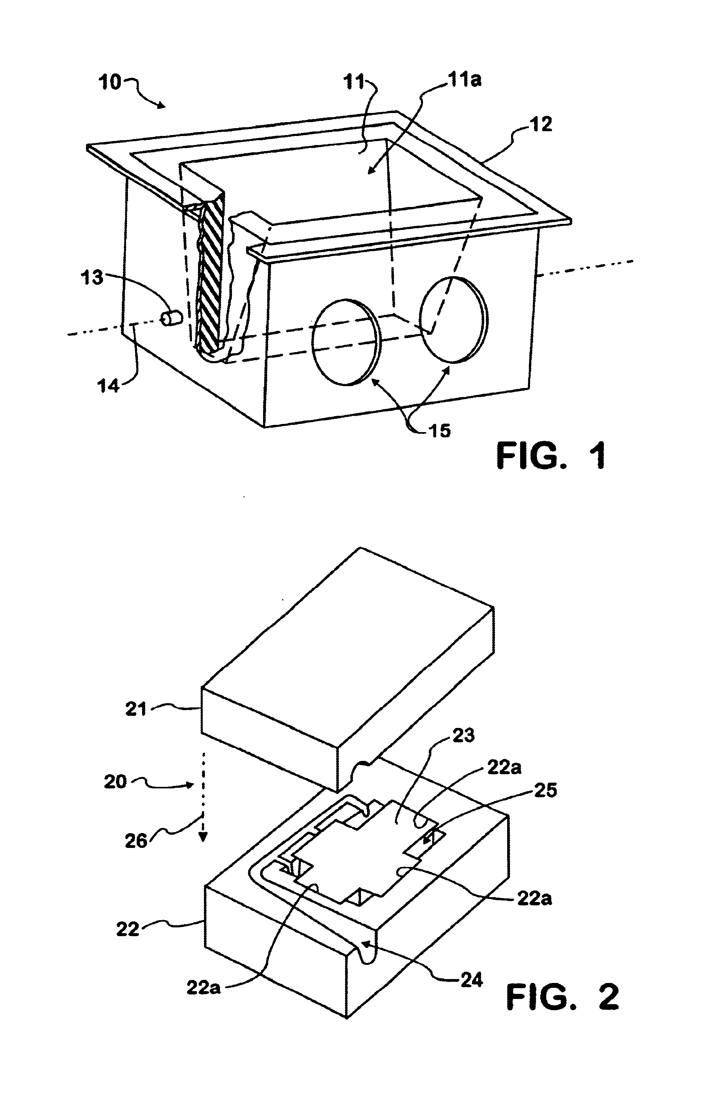
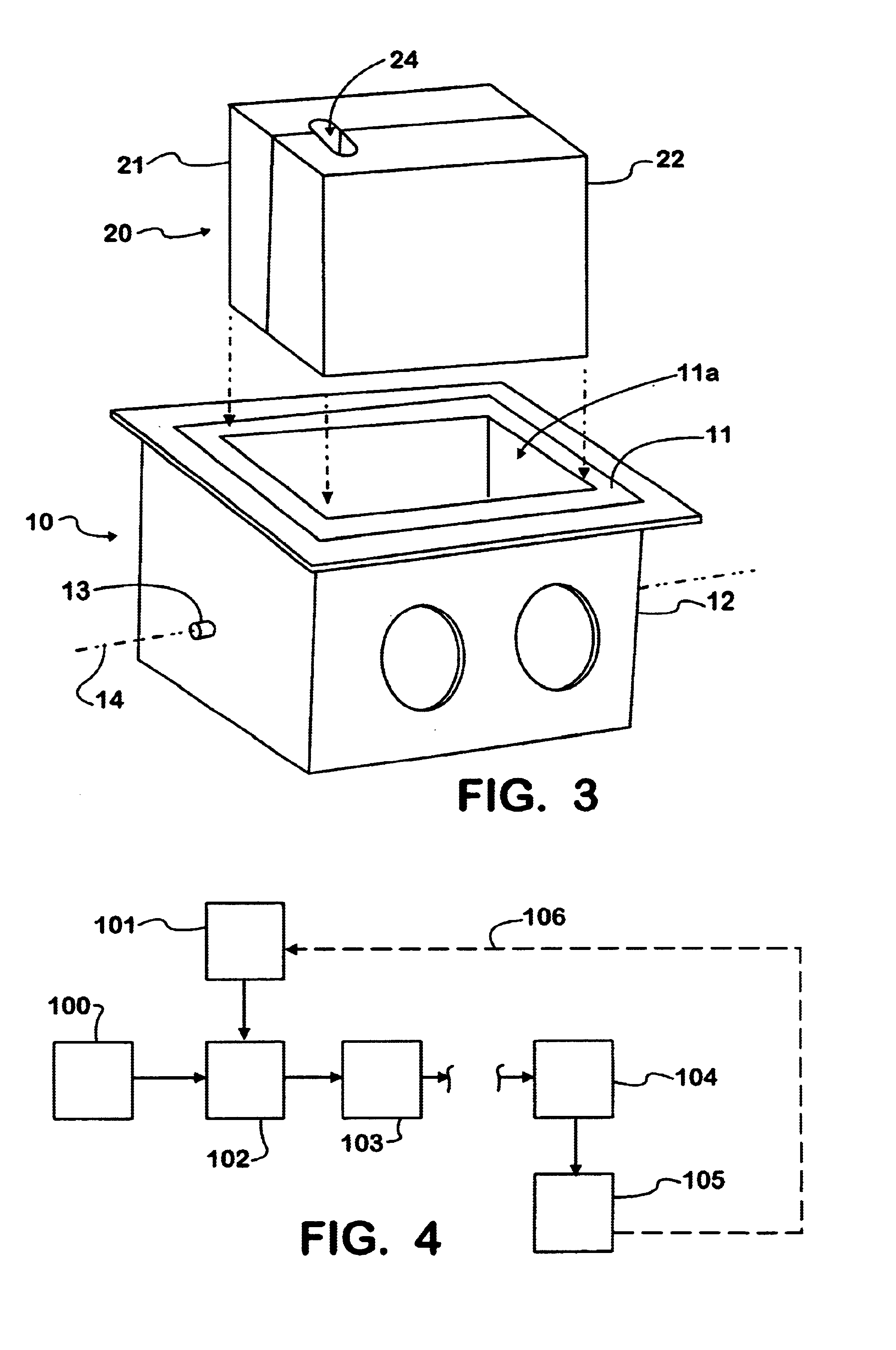
[0026]FIG. 1 is a perspective view of one embodiment of a mold-core assembly carrier 10 used in the process illustrated in the block diagram of FIG. 4. As illustrated in FIG. 1, the carrier 10 for the mold-core assembly may include a liner 11, formed from a castable refractory material such as the refractory materials used to line the furnaces of iron smelting ovens. Such a refractory liner 11 can be carried in a steel jacket 12. Although FIG. 1 illustrates steel jacket 12 as encompassing the liner 11, except at its open top, with sufficient structural strength in the refractory liner, the steel jacket may be reduced to a supporting steel frame made, for example, from angle and strap iron as shown in FIG. 5. FIG. 1 is partially broken away at one end to illustrate the refractory liner 11.

[0027]As further indicated in FIG. 1, steel jacket 12 may be provided with pivot pins 13 located on an axis of rotation 14 below the center of gravity of the carrier 10 so that the carrier 10 will i...


PUM

PropertyMeasurementUnit
Angleaaaaaaaaaa
Angleaaaaaaaaaa
Angleaaaaaaaaaa

Abstract

The use of green sand is eliminated by replacing green sand molds with all core sand assemblies that provide, during casting, both the internal and external surfaces of a casting, such as a cylinder head or engine block. In the process, a mold is formed from the same core sand that is used to form the core elements defining the internal passageways of the casting. A mold-core carrier is constructed with downwardly converging sides that hold assembled mold and core elements together, without fasteners, during transportation and pouring of the molten iron alloy into the mold-core assembly and the cooling period to form the casting. After the casting is formed, the core sand from both the mold elements and core elements is recovered, and may be recycled and processed to form further mold elements or core elements or both.

Description

[0001]This patent application is a continuation in part of U.S. patent application Ser. No. 09 / 608,176 filed Jun. 30, 2000, now U.S. Pat. No. 6,644,381, and claims the benefit of Provisional U.S. patent application Ser. No. 60 / 142,334, filed Jul. 2, 1999.FIELD OF THE INVENTION[0002]This invention relates to methods and apparatus for use in casting, particularly for use in casting large, iron alloy articles such as cylinder heads and cylinder blocks for internal combustion engines.BACKGROUND OF THE INVENTION[0003]Traditional casting methods generally employ a “green sand” mold which forms the external surfaces of the cast object and the passageways into which the molten iron alloy is poured for direction into the mold cavity. A green sand mold is a mixture of sand, clay and water that has been pressure formed into the mold element. Green sand molds have sufficient thickness so that they provide sufficient structural integrity to contain the molten metal during casting and thereby for...

Claims


Application Information

Patent Timeline
IPC IPC(8): B22C5/06B22C25/00B22C5/00B22C9/10B22D15/00B22D15/02B22D47/02B22D47/00
CPCB22C5/06B22C9/103B22C25/00B22D15/02B22D47/02
Inventor CAGLE, BILLY J.FLICK, PAUL E.PARKS, ARTHUR D.REELFS, EDWARD A.
Owner INT TRUCK INTPROP LLC
Why Eureka
Try Eureka