
Washpipe apparatus

a technology of swivel and assembly, which is applied in the direction of mechanical equipment, sealing/packing, borehole/well accessories, etc., can solve the problems of swivel seal design that has yielded less than desirable seal life or other unsatisfactory performance, and achieves the effect of increasing the life of the swivel seal assembly

Inactive Publication Date: 2005-08-02
NAT OILWELL DHT
View PDF9 Cites 51 Cited by
  • Summary
  • Abstract
  • Description
  • Claims
  • Application Information

AI Technical Summary

Benefits of technology

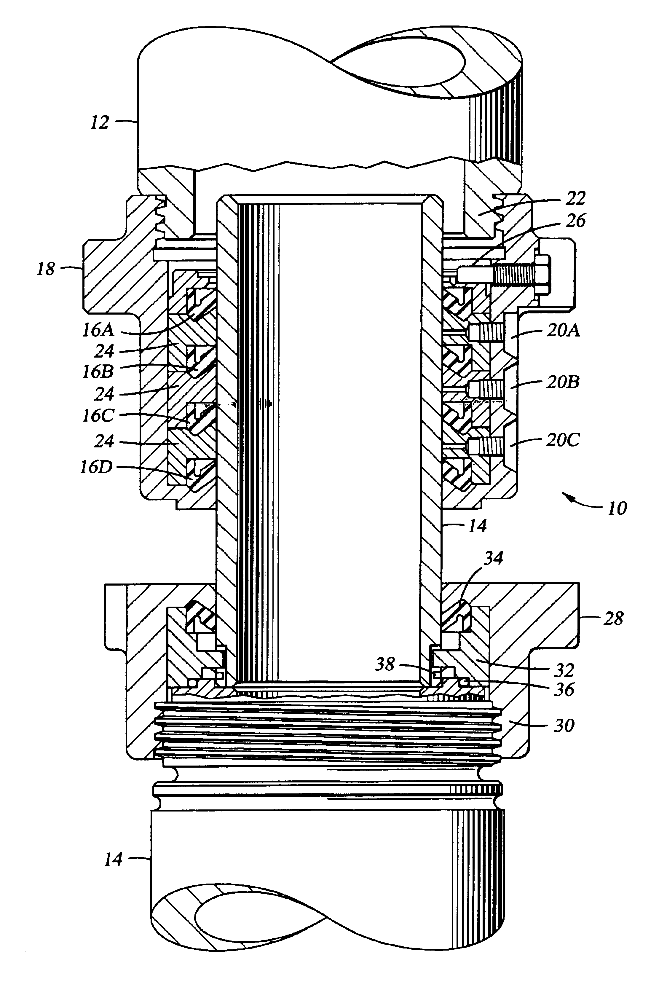
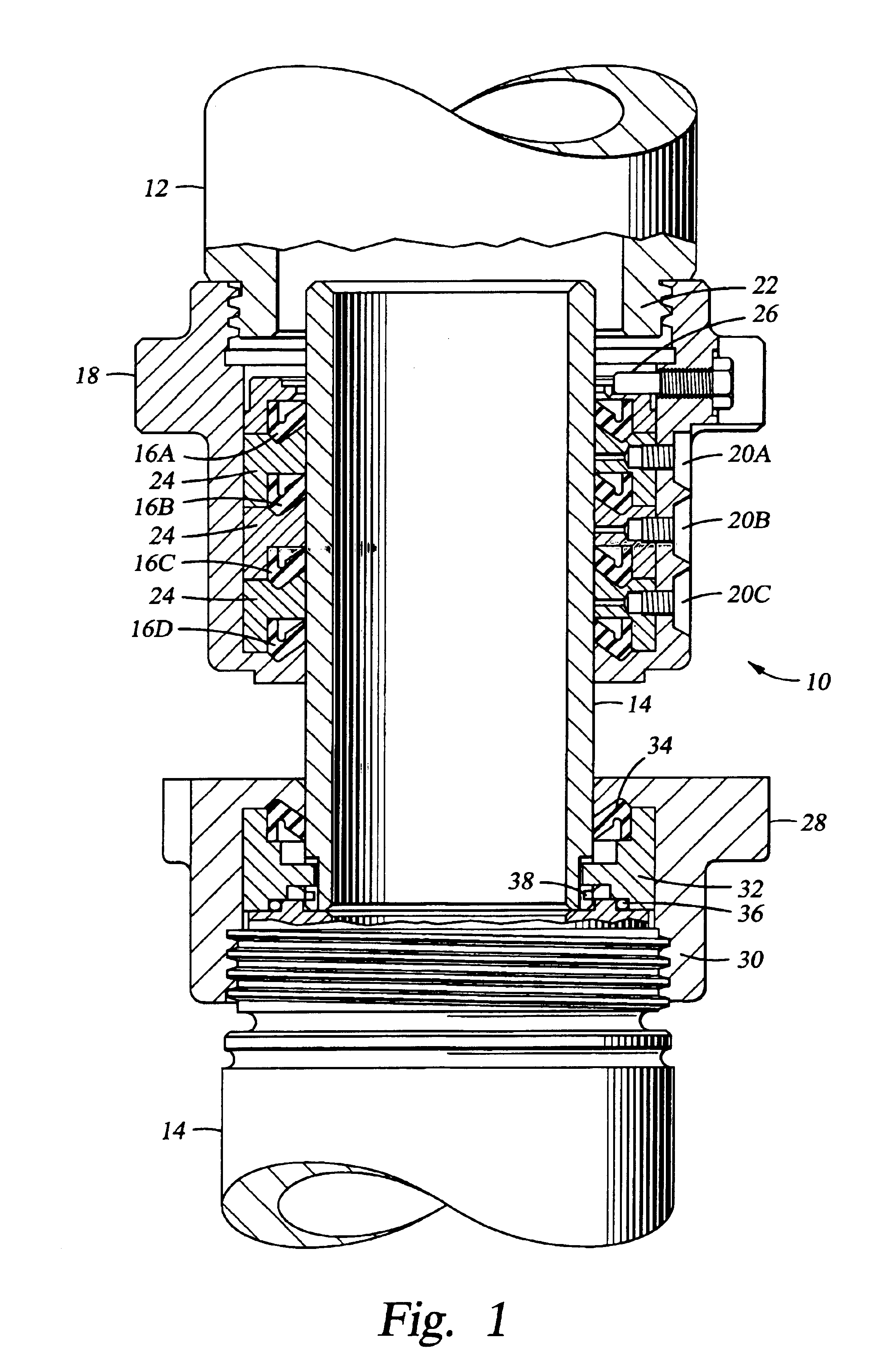
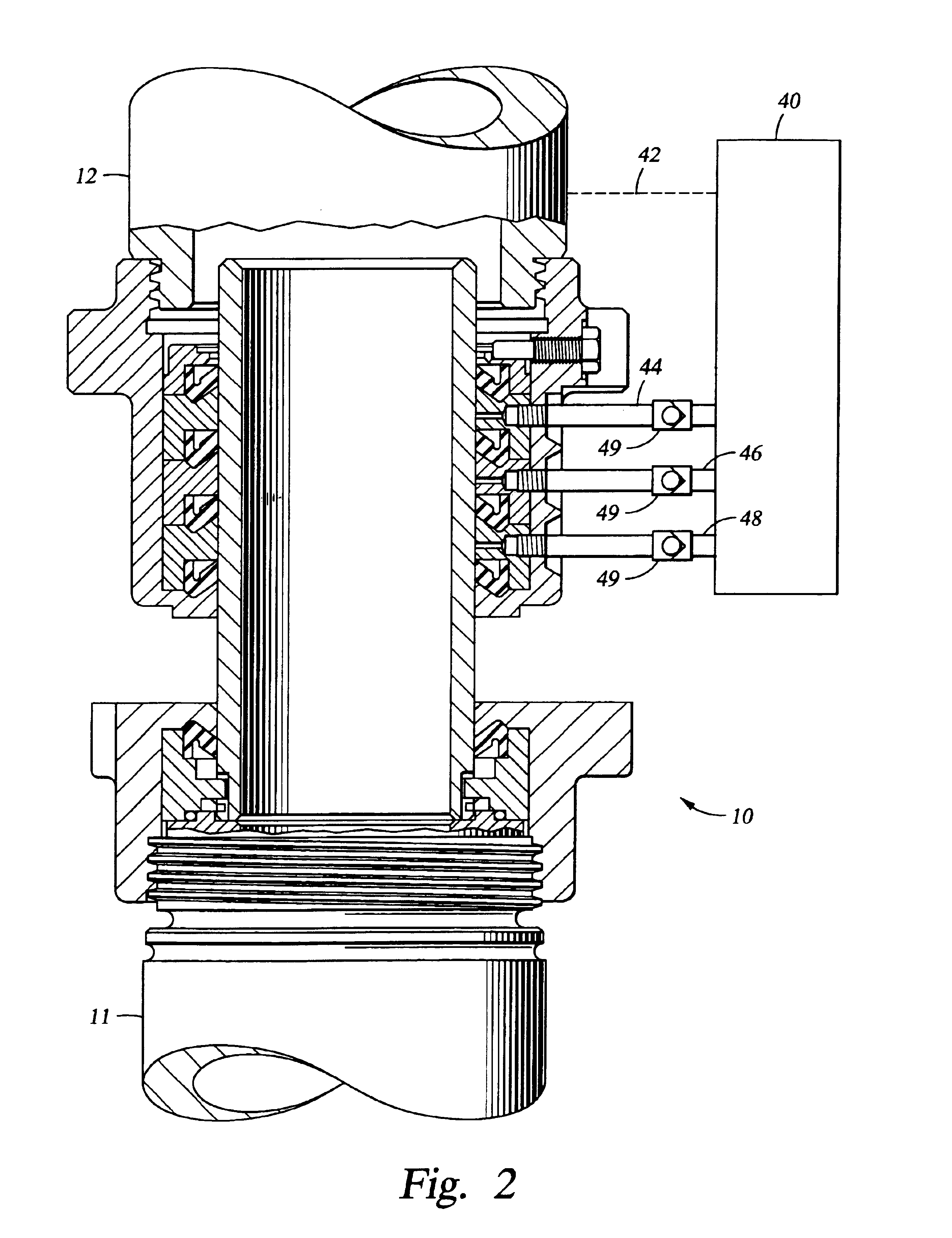
[0007]Accordingly, there are provided herein methods and apparatus for increasing the sealing life of a swivel seal assembly by decreasing the effective differential pressure across a given rotating seal. The effective differential pressure is decreased by providing a pressurized fluid on the low-pressure side of the seal at a predetermined fraction of the operating pressure of the swivel seal assembly. A preferred swivel seal assembly utilizes a washpipe and packing box that are rigidly affixed to their respective conduits. The radial misalignment and dynamic run-out is compensated for by the seal extrusion gap between the washpipe and the metal backing surfaces.
[0009]An alternative embodiment includes a method for increasing the life of a swivel seal assembly having a plurality of seals contained with a packing box and adapted to seal against a washpipe by monitoring the internal pressure of the swivel seal assembly, wherein the packing box is rigidly mounted to a stationary conduit and the washpipe is rigidly mounted to a rotating conduit, providing a pressurized fluid at a first fraction of the swivel seal internal pressure to a first annular volume between adjacent seals, and providing a pressurized fluid at a second fraction of the swivel seal internal pressure to a second annular volume between adjacent seals.

Problems solved by technology

The rotating components of the swivel are often subject to some amount of radial misalignment, or dynamic run-out, due to tolerances and inherent operating conditions.
Many conventional swivel seal designs have yielded less than desirable seal life or displayed other unsatisfactory performance in these high-pressure environments.

Method used


Image

  • Washpipe apparatus
  • Washpipe apparatus
  • Washpipe apparatus

Examples


Embodiment Construction

[0007]Accordingly, there are provided herein methods and apparatus for increasing the sealing life of a swivel seal assembly by decreasing the effective differential pressure across a given rotating seal. The effective differential pressure is decreased by providing a pressurized fluid on the low-pressure side of the seal at a predetermined fraction of the operating pressure of the swivel seal assembly. A preferred swivel seal assembly utilizes a washpipe and packing box that are rigidly affixed to their respective conduits. The radial misalignment and dynamic run-out is compensated for by the seal extrusion gap between the washpipe and the metal backing surfaces.

[0008]One preferred embodiment includes a swivel sealing assembly having a washpipe rigidly mounted to a rotating conduit and a packing box rigidly mounted to a stationary conduit. The packing box engages the washpipe such that a circulating fluid flows through the washpipe and packing box at an elevated pressure. A plurali...


PUM


Abstract

Methods and apparatus for providing enhanced seal life of a swivel seal assembly by decreasing the effective differential pressure across a given rotating seal. The differential pressure is decreased by providing a pressurized fluid on the low-pressure side of the seal at a predetermined fraction of the operating pressure of the swivel seal assembly. A preferred swivel seal assembly utilizes a washpipe and packing box that are rigidly affixed to their respective conduits such that misalignment and dynamic run-out is compensated for in the gap between the washpipe and the packing box. A control system monitors and regulates the pressurized fluid supplied to the assembly.

Description

CROSS-REFERENCE TO RELATED APPLICATIONS[0001]Not applicableSTATEMENT REGARDING FEDERALLY SPONSORED RESEARCH OR DEVELOPMENT[0002]Not applicable.BACKGROUND OF THE INVENTION[0003]The present invention relates generally to methods and apparatus for providing high pressure fluid communication between relatively rotatable, generally coaxial conduits, and in particular to washpipe assemblies such as those used in rotary drilling swivels.[0004]Rotary drilling swivels generally include a washpipe that sealingly engages a set of circumferential seals contained within a seal housing. Frequently, the washpipe remains stationary while the seals and the seal housing rotate. Swivel seal assemblies have conventionally included a series of reinforced, elastomeric, chevron-type seals interspersed with a series of reinforcing back-up rings. Generally, one seal is exposed to full hydraulic pressure on one side, and atmospheric pressure on the opposite side. These seals tend to function in a redundant m...

Claims


Application Information

Patent Timeline
Patent Type & Authority Patents(United States)
IPC IPC(8): F16L17/10F16L27/08F16L17/00F16L27/00E21B17/05E21B33/08
CPCE21B17/05F16L27/0816F16L17/10E21B33/085
Inventor MORROW, WESLEY C.DINKEL, JEFFERY J.KUBINSKI, MICHAEL J.
Owner NAT OILWELL DHT
Learn More