[0052]As is clear from the embodiments described above, the electric rotational tool driving switch
system of the present invention includes an electric motor, a rotational tool, such as a driver bit, etc., which is connected to the output shaft of this electric motor and which performs work, such as the tightening of screws, etc., a driving switch which initiates the above-described work performed by the rotational tool by driving the electric motor, a torque detection means which detects the
load torque generated in the rotational tool when the above-described work is completed, and a torque-set automatic stopping means which stops the driving of the rotational tool when the above-described load torque reaches a preset torque value; and in this structure, a driving switch of a push operating
system, which switches the electric motor ON when the rotational tool is caused to contact the work object such as a screw, etc. and displaced by being pressed, and a driving switch of a lever operating system, which switches the electric motor ON when a switch lever installed in the grip portion of the electric rotational tool is displaced by being pressed, are respectively constructed by combining magnets and magnetic sensors, and the magnetic sensors are respectively connected to the power circuit of the electric motor, so that either of the above-described operating systems can be selected, and the driving of the electric motor is initiated by switching the power circuit ON through the
magnetism sensing action of the magnetic sensor of the selected operating system. Accordingly, when the electric rotational tool is used, driving control using the desired push operating system or lever operating system can be selectively performed in accordance with the content of the work, so that an appropriate tightening work of screws, etc. can be always performed efficiently, and so that handling can be simplified and safety can be sufficiently improved.
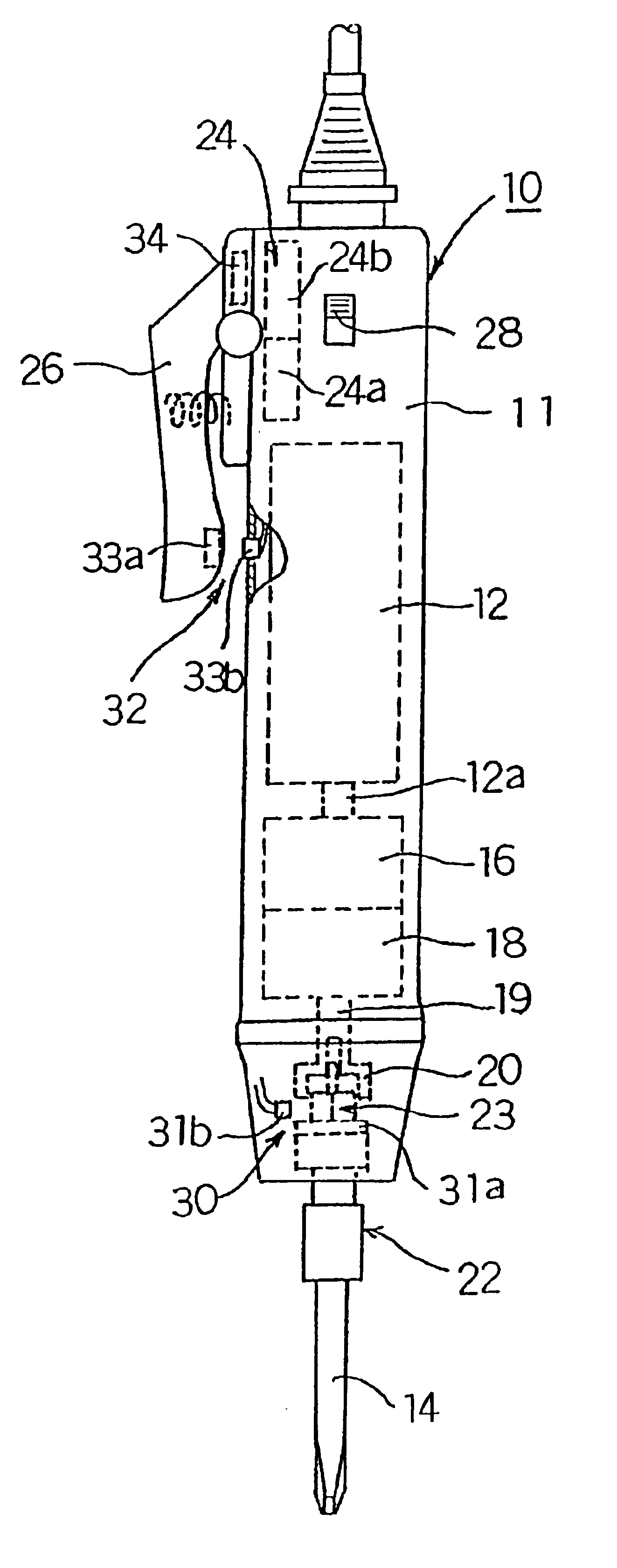
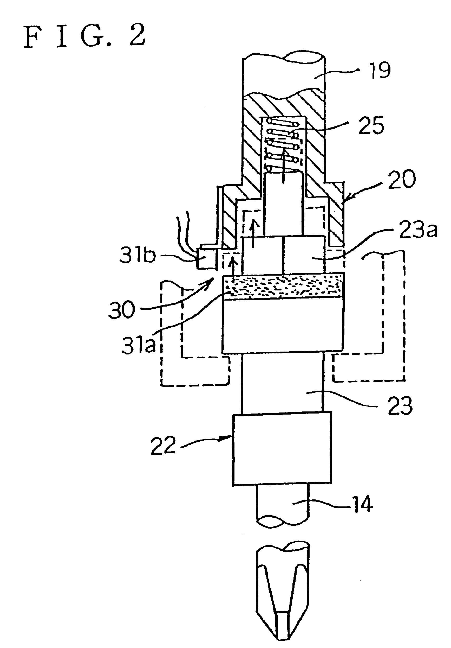
[0053]Furthermore, in the electric rotational tool driving switch system of the present invention, the above-described driving switch of the push operating system is constructed by connecting the rotational tool by a shaft
coupling so that the supporting shaft that supports the rotational tool is allowed to make elastic displacement in the axial direction, installing a
magnet in the displacement portion of this supporting shaft, and disposing a magnetic sensor in the outer circumferential portion of the supporting shaft so that this magnetic sensor faces the
magnet; the driving switch of the lever operating system is constructed by installing a magnet in the displacement portion of a switch lever installed in a portion of the grip portion casing of the electric rotational tool, and disposing a magnetic sensor on the grip portion casing side so that this magnetic sensor faces the magnet; and a selection switch is installed which allows selection so that a power circuit that initiates the driving of the electric motor can be formed by either one of the above-described operating systems. Accordingly, driving switches that allow the use of both a push operating system and a lever operating system can easily be installed in a single electric rotational tool by a simple structure. Especially in cases where a brushless motor is used as the electric motor, numerous superior advantages can be obtained: e.g., the driving switches can both be accommodated in a compact manner inside the grip portion casing of the electric rotational tool together with the driving
control circuit of the electric motor, a long useful life and maintenance-free operation based on overall non-contact operation can be realized, and handling can be simplified.
[0054]Furthermore, in the electric rotational tool driving switch system of the present invention, a forward-reverse conversion switch that can be operated from the outside is disposed in a portion of the grip portion casing of the electric rotational tool; and in cases where the electric motor is converted from forward rotation to reverse rotation when work, such as removing of screws, etc., is performed, the power circuit is set so that the driving of the electric motor by the push operating system is disabled, and the power circuit is set so that the driving of the electric motor is initiated only by the lever operating system. Accordingly, in cases where work, such as removing of screws, etc., is performed, the driving of the electric motor 12 is stopped by manual release of the lever operation in accordance with the visual and tactile
sensory functions of the operator when the removal of the screw is completed. Consequently, problems such as generation of
cutting debris by idling of the rotational tool with the screw can be prevented, and accurate and safe work can be accomplished.
[0055]Furthermore, in the electric rotational tool driving switch system of the present invention, a
clutch mechanism can be utilized as a torque detection means installed in the grip portion casing; and in this case, the torque adjustment mechanism that acts on the
clutch mechanism is disposed protruding at a slight inclination with respect to the supporting shaft of the rotational tool that protrudes vertically downward from the grip portion casing. Accordingly, the grip portion casing can be set at minimum dimensions, the combined installation of the driving switches and torque adjustment mechanism can be facilitated, operation of the tool and maintenance work can be smoothly performed without the rotational tool and torque adjustment mechanism having any effect on each other, and an electric rotational tool with easy handling is obtainable.

