Sensor read out

a technology of electronic sensors and sensors, applied in differential amplifiers, dc-amplifiers with dc-coupled stages, amplifiers, etc., can solve the problem of quite limited time constant of filters

Inactive Publication Date: 2005-08-02
DIALOG SEMICONDUCTOR GMBH
View PDF9 Cites 33 Cited by
  • Summary
  • Abstract
  • Description
  • Claims
  • Application Information

AI Technical Summary

Problems solved by technology

There are various problems linked to this prior art approach.
The voltage modulation of the voltages measured at port 4 and 5 is huge and therefore the time constant of a filter is quite limited.

Method used


Image

  • Sensor read out
  • Sensor read out
  • Sensor read out

Examples


Embodiment Construction

[0023]The preferred embodiment disclose a method and a circuit capable to measure continuously the variable resistance of resistors as being used e.g. in combination with joysticks.

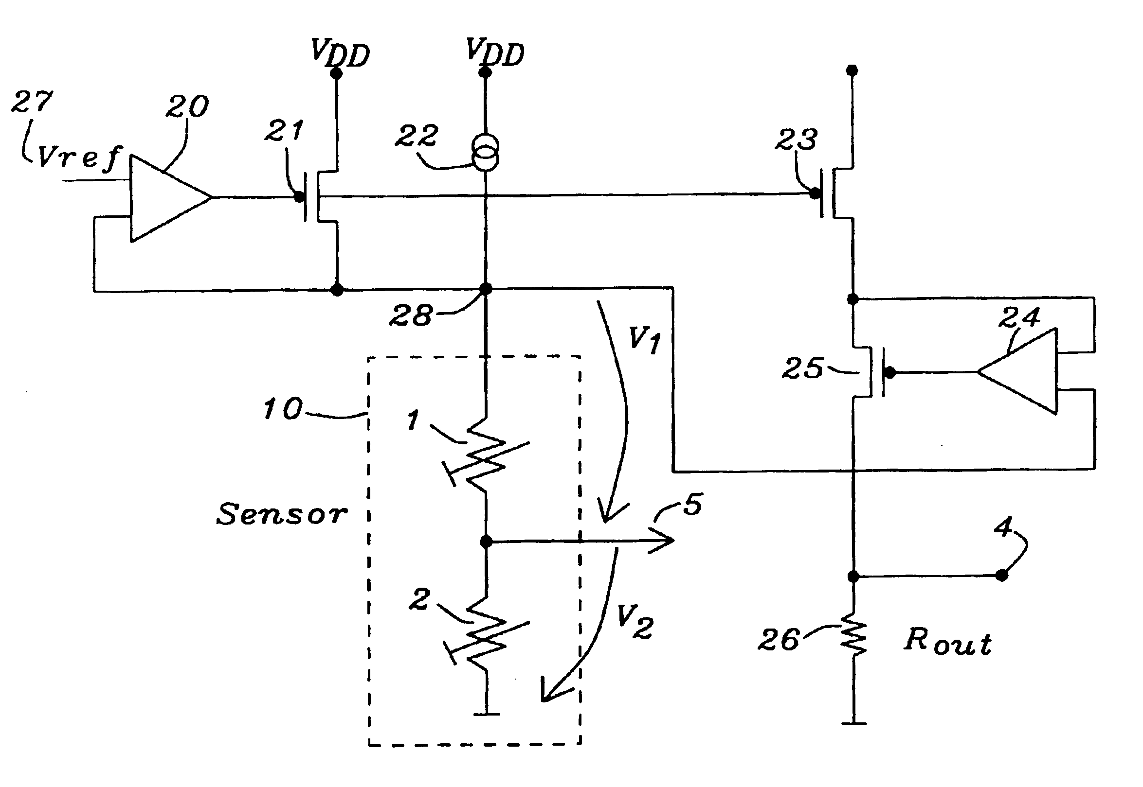
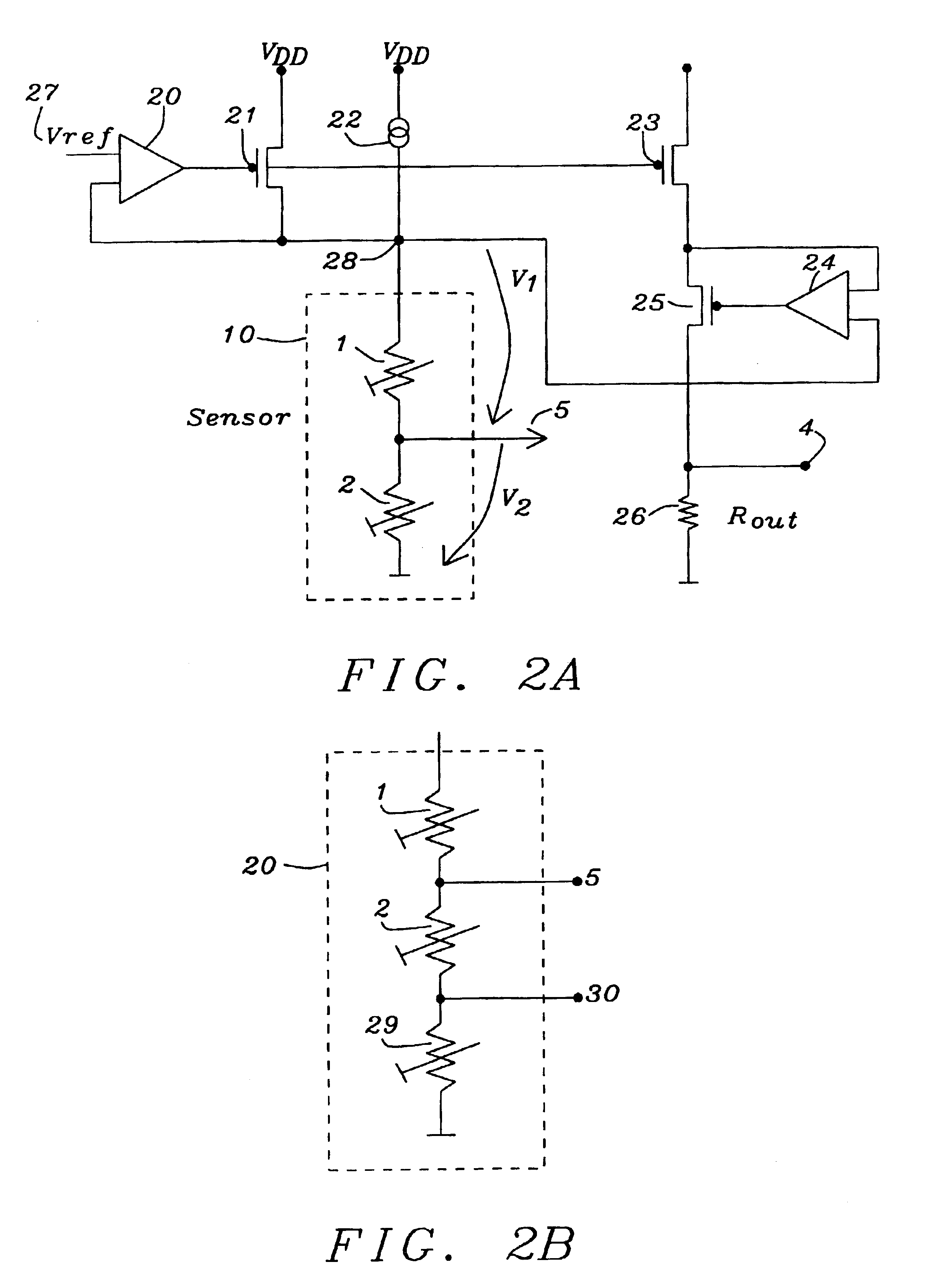
[0024]FIG. 2A shows a schematic of the circuit invented. The voltage across the sensor 10 is stabilized. This is performed by the amplifier 20 and the transistor 21 using a reference voltage 27. The constant current source 22 is only required to zoom out the variations of the resistance Z of the sensor 10 and is providing a constant part of the current flowing through said sensor 10. Said sensor 10 comprises two variable resistors 1 and 2.

[0025]For example, if the current flowing through the sensor is 1 mA and the current source 22 is providing a constant current of 950 μA, a current of only 50 μA will flow through transistor 21. In case the current through said sensor 10 increases by 10 μA, said current through transistor 21 will increase subsequently from 50μ to 60 μA. This is a change of 20%. Without t...


PUM

PropertyMeasurementUnit
currentaaaaaaaaaa
currentaaaaaaaaaa
currentaaaaaaaaaa

Abstract

A circuit and a method to measure continuously the resistance of variable resistors in series as e.g. potentiometers within a sensor, used for e.g. a joystick, has been achieved. The voltage across said sensor comprising any number of variable resistors is stabilized. A constant current source is providing a minimum current through said sensor. A variable current source is used to zoom variations of current through the sensor caused by variations of resistance of the sensor. Said variable current is mirrored and by measuring the voltage across a shunt resistor the total resistance of the sensor is identified. Using ports between each of the resistors, voltages can be measured representing the resistance of each of the variable resistors using known equations of voltage dividers. Any number of variable resistors can be used in the circuit invented.

Description

BACKGROUND OF THE INVENTION[0001](1) Field of the Invention[0002]This invention relates generally to the area of reading out electronic sensors, and more particular, to sensors having variable resistance as e.g. potentiometers.[0003](2) Description of the Prior Art[0004]One of the most convenient and inexpensive transducer is a potentiometer. A potentiometer is essentially a device, which can be configured so that a continuously variable voltage is produced that is proportional to the potentiometer's shaft position.[0005]One of the applications of potentiometers is the usage as an analog input device in combination with devices as a joystick. A joystick position is determined by reading the resistance value of a potentiometer attached to the joystick. Potentiometers are a simple and very inexpensive system and can be designed to interface to a standard computer interface. Potentiometers can use a desktop as a position reference, and a joystick is usually suction or non-skid mounted ...

Claims


Application Information

Patent Timeline
Patent Type & Authority Patents(United States)
IPC IPC(8): G01D3/02G01D5/165G01D5/12G01R17/20G01R17/00G01R27/02G01R27/08
CPCG01D3/021G01D5/165G01R17/20A61B50/13
Inventor KNOEDGEN, HORST
Owner DIALOG SEMICONDUCTOR GMBH
Why Eureka
Try Eureka