Method and apparatus for aligning a cassette

a cassette and cassette technology, applied in the field of automatic workpiece handling systems, can solve the problems of inconvenient operation, high accuracy of blade moving mechanisms, and many drawbacks of these tools, and achieve the effects of facilitating rapid and accurate facilitating the performance of alignment and height setting procedures, and increasing the accuracy of those procedures

Inactive Publication Date: 2005-08-02
APPLIED MATERIALS INC
View PDF1 Cites 35 Cited by
  • Summary
  • Abstract
  • Description
  • Claims
  • Application Information

AI Technical Summary

Benefits of technology

[0012]The present inventions are, in one aspect, directed to an alignment tool, method and system for aligning a cassette handler to a robot blade in a workpiece handling system, in which the tool comprises a frame or fixture adapted to be supported by the cassette handler support surface, in which the frame has one or more distance sensors positioned to measure the distance of a workpiece or robot blade from the sensor or a predetermined reference point or surface. In a preferred embodiment, the frame emulates a workpiece cassette and the distance sensors provide a numerical output of the distance to the workpiece. As explained in greater detail below, these distance measurements facilitate accurately leveling the cassette handler support surface relative to a workpiece supported by the robot blade such that when the frame is replaced by an actual workpiece cassette, the workpiece cassette will also be level with respect to the robot blade and the workpiece held by the blade. As a consequence, accidental scratching and breakage of workpieces such as semiconductor wafers and display substrates may be reduced or eliminated.
[0015]In still another aspect of the present inventions, the frame has a predetermined reference surface positioned opposite the distance sensors of the frame. In a preferred embodiment, the frame reference surface is accurately positioned by the frame to be at a predetermined orientation and distance from a cassette handler reference point or surface such as the cassette handler support surface. As a consequence, as explained in greater detail below, distance measurements to the workpiece or robot blade may be output as offsets from this predetermined frame reference surface which significantly facilitates calibrating the distance sensors.
[0017]In still another aspect of the present inventions, the frame has a plurality of sets of registration surfaces which are each adapted to register the frame to the cassette handler support surface. As a consequence, the frame may be seated in the cassette handler in a plurality of orientations. As explained below, such an arrangement facilitates performing alignment and height setting operations at widely spaced blade height positions to increase the accuracy of those procedures.
[0018]In yet another aspect of the present inventions, a preferred embodiment includes a computer operated graphical user interface which can significantly facilitate rapid and accurate performance of alignment and setting procedures utilizing the alignment frame of the present inventions. As set forth below, the computer assisted embodiments can perform various calculations including preferred blade height positions such as the slot base and slot delta positions and elevator characterizations for example. Actual measurements may be compared to preferred values calculated or otherwise provided and appropriate adjustments made.

Problems solved by technology

However, typical prior methods for aligning the handler and cassette to the robot blade have generally been relatively imprecise, often relying upon subjective visual inspections of the clearances between the various surfaces.
However, many of these tools have a number of drawbacks.
Such contact can be very detrimental to high precision mechanisms for moving the blade as well as the blade itself.
In addition to being very subjective, such bubble tools have also often been difficult to see in the close confines of the cassette and handler mechanisms.
As a consequence of these and other deficiencies of the prior alignment procedures and tools, alignments have often tended to be not only imprecise but also inconsistent from application to application.
These problems have frequently lead to the breakage or scratching of very expensive wafers and equipment as well as the generation of damaging particulates in the systems.

Method used


Image

  • Method and apparatus for aligning a cassette
  • Method and apparatus for aligning a cassette
  • Method and apparatus for aligning a cassette

Examples


Embodiment Construction

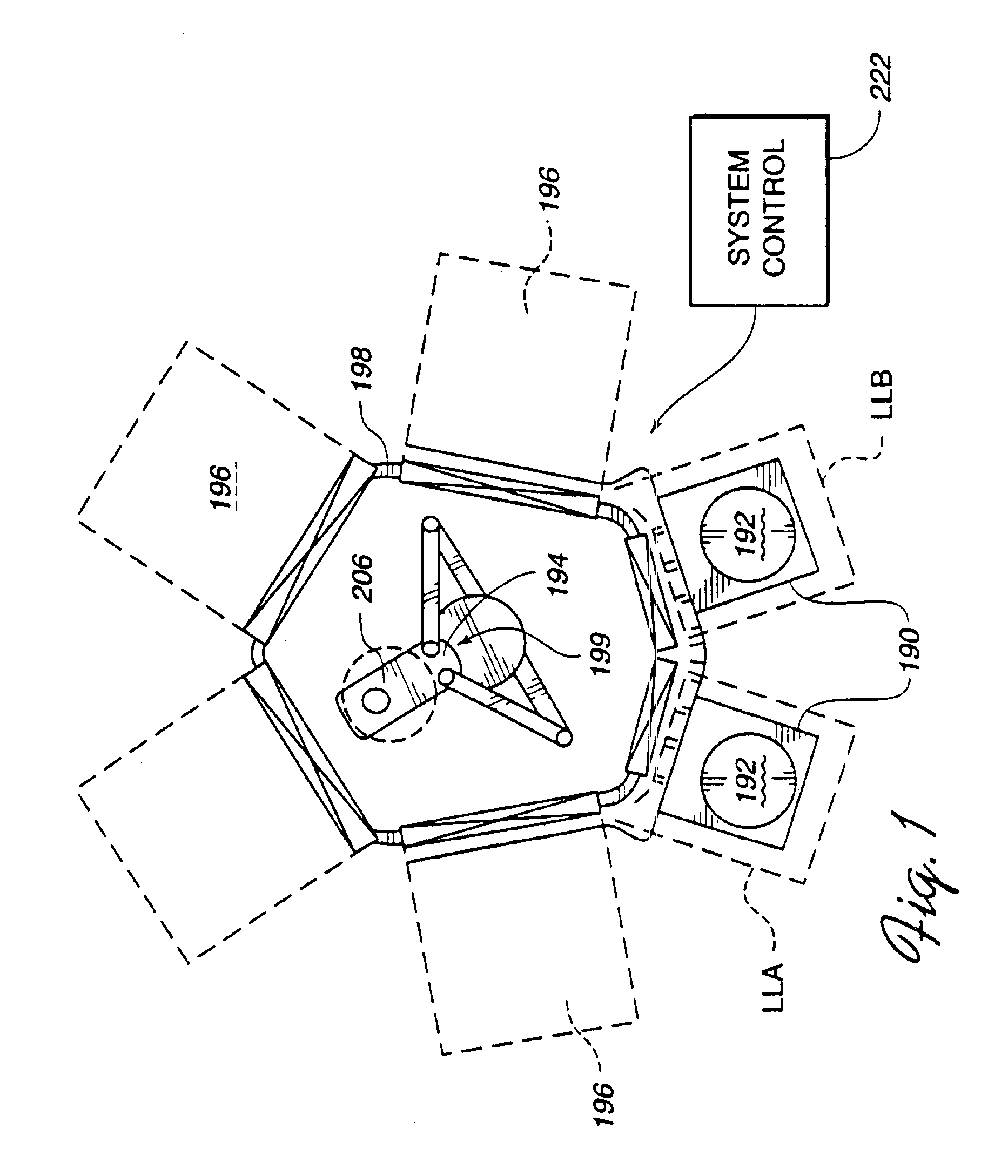
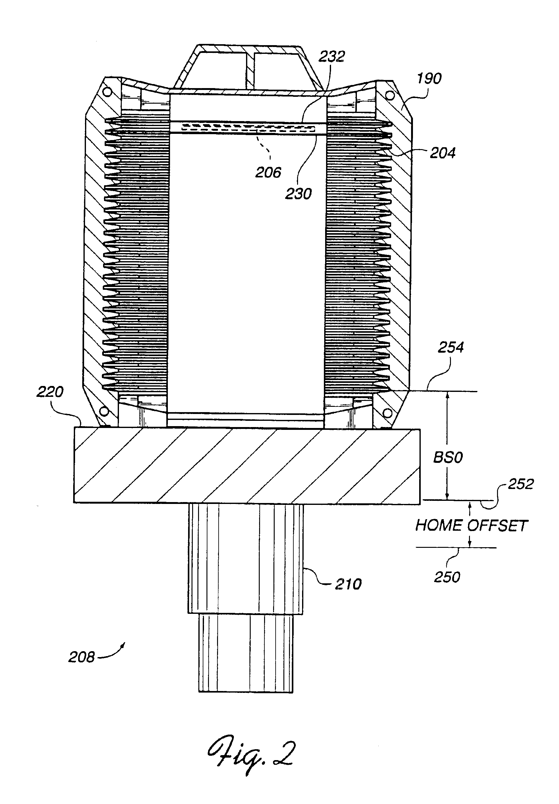
[0053]A cassette alignment tool system in accordance with a preferred embodiment of the present invention is indicated generally at 400 in FIG. 4. The cassette alignment tool 400 comprises a metrology cassette 410, cassette controller 412 coupled by a communication cable 414 to the metrology cassette 410, and a computer 416 coupled by a communication cable 418 to the cassette controller 412. The metrology cassette 410 is secured to the cassette handler platform 200 in the same manner as an actual wafer cassette such as the cassette 190 of FIG. 2 and thus emulates the wafer cassette 190. For example, the metrology cassette has alignment and registration surfaces including an H-bar 430 and side rails 570 which are received by the cassette handler to align the cassette with respect to the handler. In addition, the metrology cassette 410 approximates the size and weight of a production wafer cassette full of wafers.

[0054]The cassette alignment tool system 400 may be used with processing...


PUM


Abstract

An alignment tool, method and system are provided for aligning a cassette handler to a robot blade in a workpiece handling system, in which the tool comprises a frame or fixture adapted to be supported by the cassette handler support surface, in which the frame has one or more distance sensors positioned to measure the distance of a workpiece or robot blade from the sensor or a predetermined reference point or surface. In a preferred embodiment, the frame emulates a workpiece cassette and the distance sensors provide a numerical output of the distance to the workpiece. As explained in greater detail below, these distance measurements facilitate accurately leveling and aligning the cassette handler support surface relative to a workpiece supported by the robot blade such that when the frame is replaced by an actual workpiece cassette, the workpiece cassette will also be level and aligned with respect to the robot blade and the workpiece held by the blade. As a consequence, accidental scratching and breakage of workpieces such as semiconductor wafers and display substrates may be reduced or eliminated.

Description

[0001]This application is a continuation of U.S. application Ser. No. 09 / 294,301 filed Apr. 19, 1999, now abandoned, which is incorporated herein by reference in its entirety.FIELD OF THE INVENTION[0002]The present invention relates to automated workpiece handling systems, and more particularly, to methods and devices for aligning a cassette for workpieces in an automated workpiece handling system.BACKGROUND OF THE INVENTION[0003]In order to decrease contamination and to enhance throughput, semiconductor processing systems often utilize one or more robots to transfer semiconductor wafers, substrates and other workpieces between a number of different vacuum chambers which perform a variety of tasks. An article entitled “Dry Etching Systems: Gearing Up for Larger Wafers”,n in the October, 1985 issue of Semiconductor International magazine, pages 48-60, describes a four-chamber dry etching system in which a robot housed in a pentagonal-shaped mainframe serves four plasma etching chambe...

Claims


Application Information

Patent Timeline
Patent Type & Authority Patents(United States)
IPC IPC(8): B23Q17/24B23Q3/18H01L21/67H01L21/677H01L21/00H01L21/68H01L21/673
CPCB23Q3/186B23Q17/24H01L21/67259H01L21/67265H01L21/67379H01L21/67775H01L21/68H01L21/681H01L21/6732Y10S414/136
Inventor SCHAUER, RONALD VERNLAPPEN, ALAN RICKTUTTLE, DAVID L.
Owner APPLIED MATERIALS INC
Why Eureka
Try Eureka