Practical pseudo-asynchronous filter architecture

a filter architecture and pseudo-asynchronous technology, applied in the field of filters, can solve the problems of reducing affecting the efficiency affecting the accuracy of the data, so as to reduce the number of filters required to accommodate the data requirements of the secondary process, reduce the number of processor requirements, and avoid computationally intensive and complicated variable rate filters

Inactive Publication Date: 2005-08-02
NIKON CORP
View PDF12 Cites 12 Cited by
  • Summary
  • Abstract
  • Description
  • Claims
  • Application Information

AI Technical Summary

Benefits of technology

[0010]In another embodiment, the synchronous filters are programmable so as to change the filter update time. This configuration is possible when it is known that the frequency at which the secondary process requires data from the filter (the input frequency) is smaller than the filter update frequency and the filter update frequency is an integer multiple of the input frequency. By using programmable filters, the number of filters required to accommodate the data requirements of the secondary process can be minimized.
[0011]Whether a system employs multiple non-programmable filters staggered in time or programmable filters, the invention achieves a variable rate filtered output while using synchronous filters. Thus, computationally intensive and complicated variable rate filters can be avoided, while at the same time minimizing processor requirements.
[0012]In another aspect of the invention, a method of generating a variable rate filtered output is employed in a lithography system to control the movements of various components therein. In one embodiment, the filtered outputs are used to estimate the position of the wafer stage. With the variable rate feature, the lithography system, in which the correction subsystem can only accept stage state information within restricted windows in time and the rate at which these windows occur is not constant, can dynamically correct for the position errors in the stage during the wafer exposure process.

Problems solved by technology

Filtering is necessary because measurement of physical phenomena (e.g., position, velocity, acceleration and pressure) usually results in a signal that is corrupted by noise and other sources of deviations from the actual measurement desired.
The secondary process typically cannot meaningfully use noisy sensor samples.
Furthermore, the window during which the secondary process may accept information from the filter may be restricted.
Unfortunately, asynchronous Kalman filters are typically very complicated and, consequently, computationally intensive and slow.
The intensive computational requirements of an asynchronous Kalman filter will limit the maximum sampling frequency.
As a result, the asynchronous filter may be unable to produce an output at a rate necessary for the secondary process.
More details on synchronous Kalman filters can be found in Adaptive Filtering: Prediction and Control by Graham C. Goodwin and Kwai Sang Sin, Prentice-Hall, Inc., Englewood Cliffs, N.J. Unfortunately, a single synchronous Kalman filter is not well suited to applications that require filtered output at a variable rate.

Method used


Image

  • Practical pseudo-asynchronous filter architecture
  • Practical pseudo-asynchronous filter architecture
  • Practical pseudo-asynchronous filter architecture

Examples


Embodiment Construction

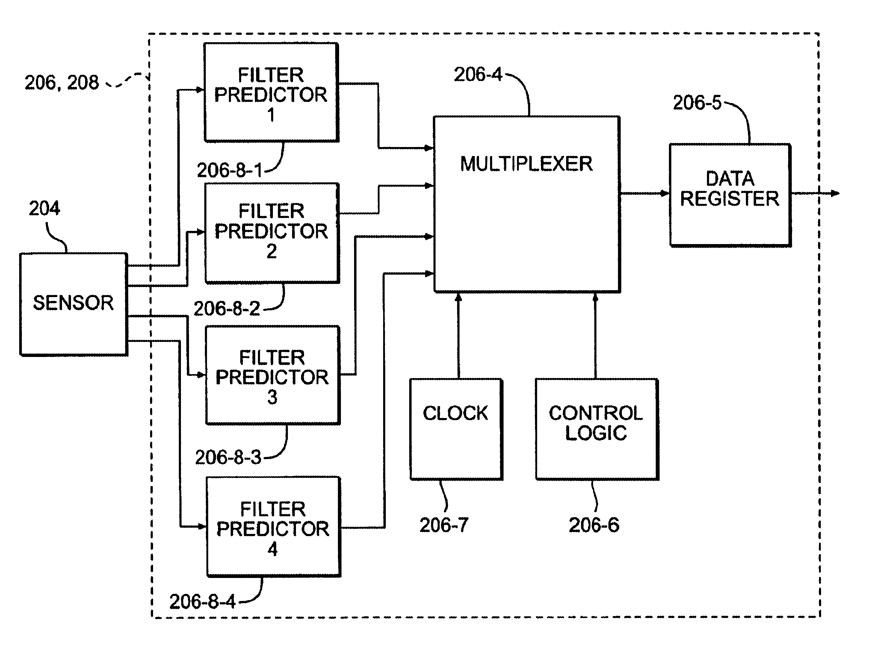
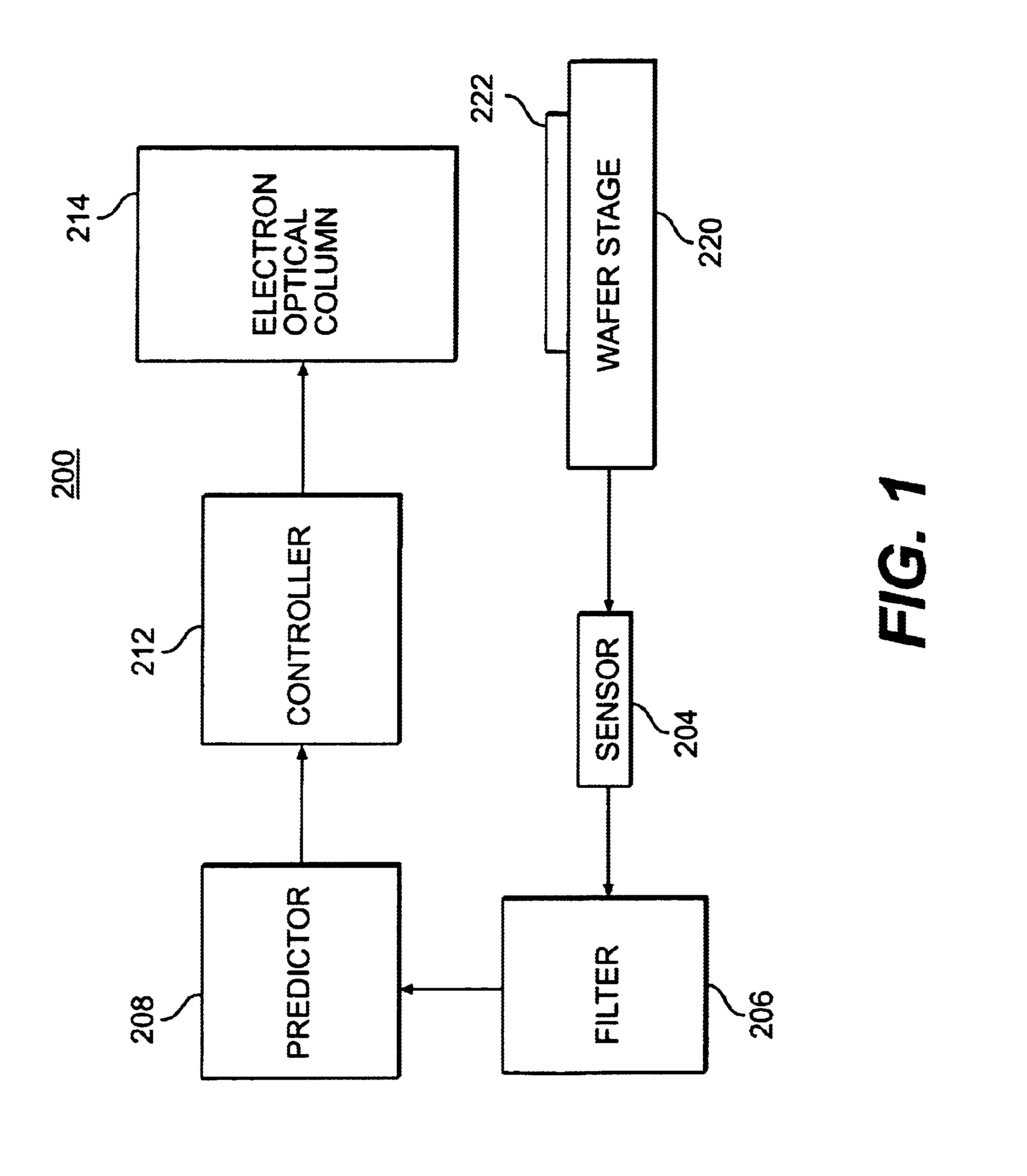
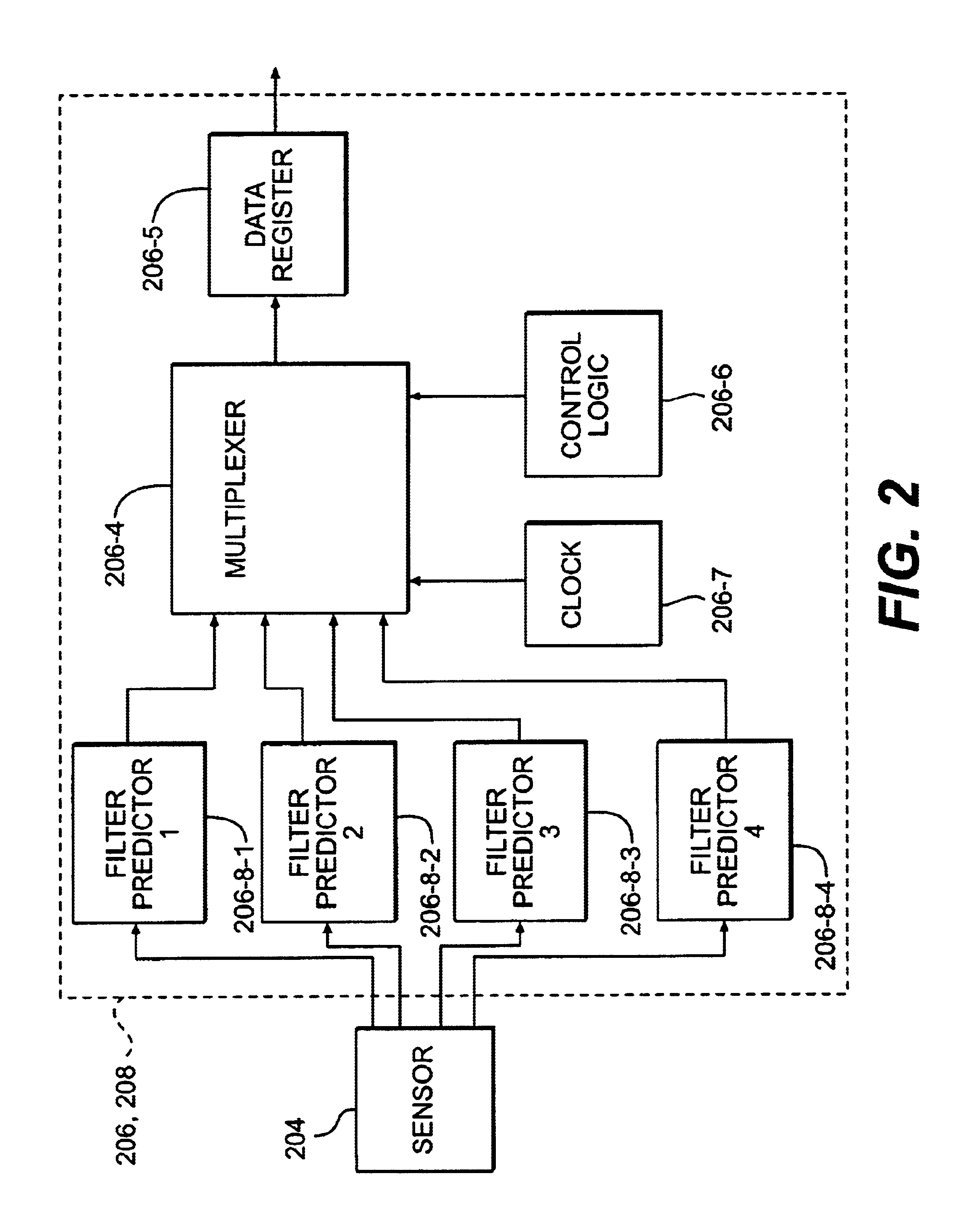
[0023]FIG. 1 shows a system block diagram of an electron beam lithography system (System) 200 according to the presently preferred embodiment of the invention. System 200 includes a moving stage 220 that carries a resist-coated wafer 222 for exposure by an electron optical column 214. System 200 also includes a sensor 204 that measures the position of the wafer stage 220. The sensor 204 is coupled to a filter 206. The filter 206 is connected to a predictor 208 that in turn is connected to a controller 212. The controller 212 is connected to the electron optical column 214. The filter 206 and the predictor 208 are shown as separate units in FIG. 1; however, they may also be implemented together as a single unit. A controller (not shown) uses the output of the sensor 204 to control the position of the stage 220.

[0024]The filter 206 in the preferred embodiment of the invention is a Kalman filter; however, other filters may be used, such as a lattice filter or a finite impulse response ...


PUM


Abstract

A system and methods for generating a variable rate filtered output using synchronous filters having the same filter sampling time, that avoids complexities of asynchronous filters. A system employs multiple filters that are staggered in time and set so that the output of one of the multiple filters is available whenever a secondary process requires state information. In another embodiment, the synchronous filters are programmable so as to change the filter sampling time. This configuration is possible when it is known that the prescribed time interval of the secondary process is longer than the filter sampling time and the prescribed time interval is an integer multiple of the filter sampling time. By using programmable filters, the number of filters required to accommodate a certain prescribed time interval can be minimized. Whether a system employs multiple non-programmable filters staggered in time or programmable filters, the invention achieves producing a variable rate filtered output while using synchronous filters. Thus, computationally intensive and complicated variable rate filters can be avoided while minimizing processor requirements. In another aspect of the invention, the inventive method of generating a variable rate filtered output is employed in a lithography system to control the movements of various components therein. In one embodiment, the filtered outputs are used to estimate the relative positions of the reticle and the wafer. With the variable rate feature, the lithography system can dynamically accommodate for the noise arising from component movements and other sources in the wafer exposure process.

Description

FIELD OF THE INVENTION[0001]The invention relates to the field of filters, and more particularly to digital filters that can produce an output at a variable rate.BACKGROUND OF THE INVENTION[0002]Asynchronous digital filters are used in many applications, including navigation, process control and machine calibration. Asynchronous filters provide a filtered output of an input signal at a variable rate, hence the asynchronous appellation (i.e., filter output is available on demand). In contrast, synchronous filters provide a filtered output at a constant rate. In the area of position control, for example, the input signal to the filter may be a sensor sample that is a measurement of velocity, position, rotational rate or angle of a spinning vehicle or body. The filter output gives an indication of the orientation or trajectory of the vehicle or body. The orientation or the trajectory of a body is often described by a fixed number of variables defined as the state of the system being ob...

Claims


Application Information

Patent Timeline
Patent Type & Authority Patents(United States)
IPC IPC(8): H03H17/02G01D3/028H03H17/06
CPCH03H17/0294
Inventor JABBARI, ALIREZASTUMBO, DAVID PSOGARD, MICHAEL
Owner NIKON CORP
Why Eureka
Try Eureka