Oxygen monitoring device

a technology of oxygen monitoring and gas detection, which is applied in the direction of fluorescence/phosphorescence, instruments, specific gravity measurement, etc., can solve the problems of high cost, potential explosion of fuel tanks within fuel tanks upon ignition, and the number of aircraft fuel tanks that have unexpectedly exploded, so as to minimize the introduction of elements

Inactive Publication Date: 2005-08-09
SUSKO KENNETH
View PDF10 Cites 48 Cited by
  • Summary
  • Abstract
  • Description
  • Claims
  • Application Information

AI Technical Summary

Benefits of technology

[0009]The present invention fills the aforementioned needs by providing a method and apparatus for maintaining a temperature of a gas sensing device which measures gas levels within a chamber which minimizes the introduction of elements which may ignite a medium within the chamber.
[0013]As may be appreciated, the present invention provides a method and apparatus for maintaining a temperature of a gas sensor within a chamber while minimizing the introductions of elements which may combust flammable material located within the chamber.

Problems solved by technology

Since 1959, a number of aircraft fuel tanks have unexpectedly exploded.
The presence of both a flammable gas and the fuel / vapor mixture within the space creates the potential for an explosion within the fuel tank upon ignition.
Nonetheless, the need to continuously fill the fuel tank with an inert gas and the attendant high costs associated therewith do not make this an attractive alternative for aircraft manufacturers.
However, temperatures of fuel tanks in vehicles tend to fluctuate depending on the outside temperature.
However, these methods are not suitable for use in fuel tanks, as electrical current applied to the electrical resistance heaters may potentially ignite the fuel / vapor mixture within the tank, again making this an unattractive option for aircraft manufacturers.

Method used


Image

  • Oxygen monitoring device
  • Oxygen monitoring device
  • Oxygen monitoring device

Examples


Embodiment Construction

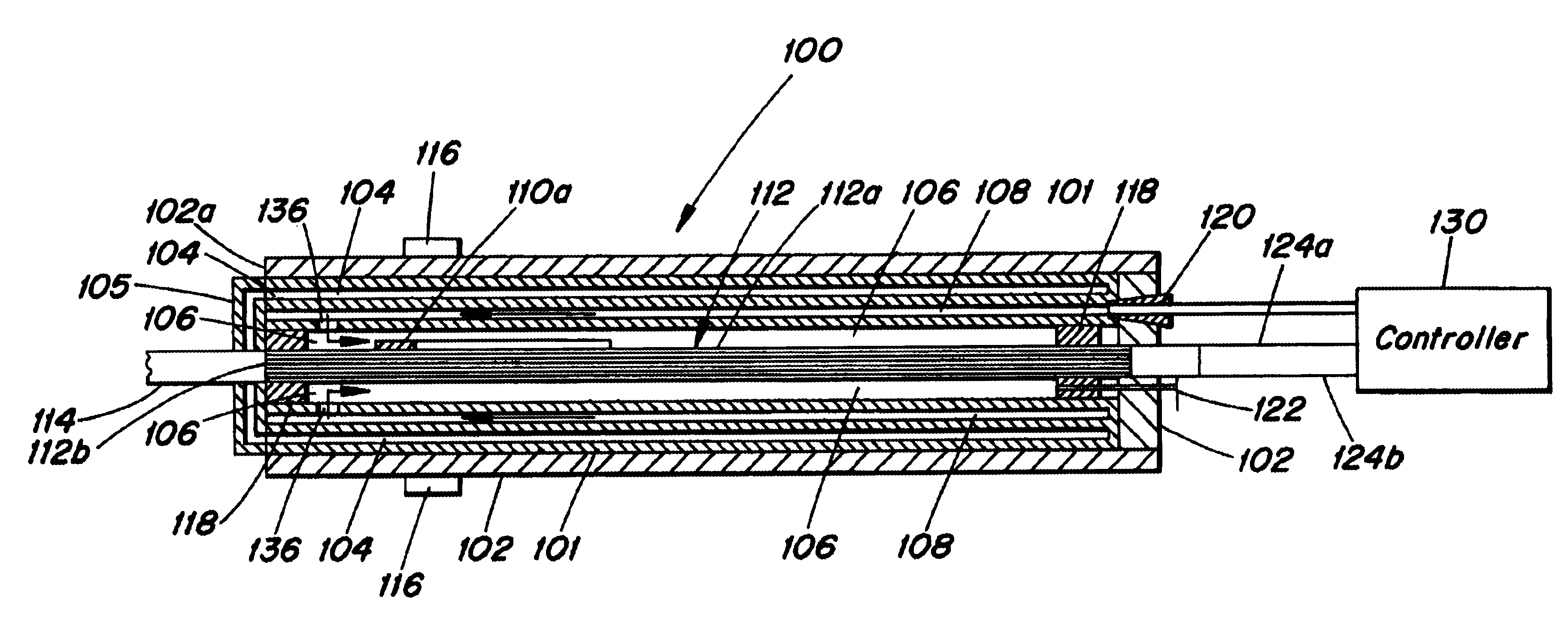
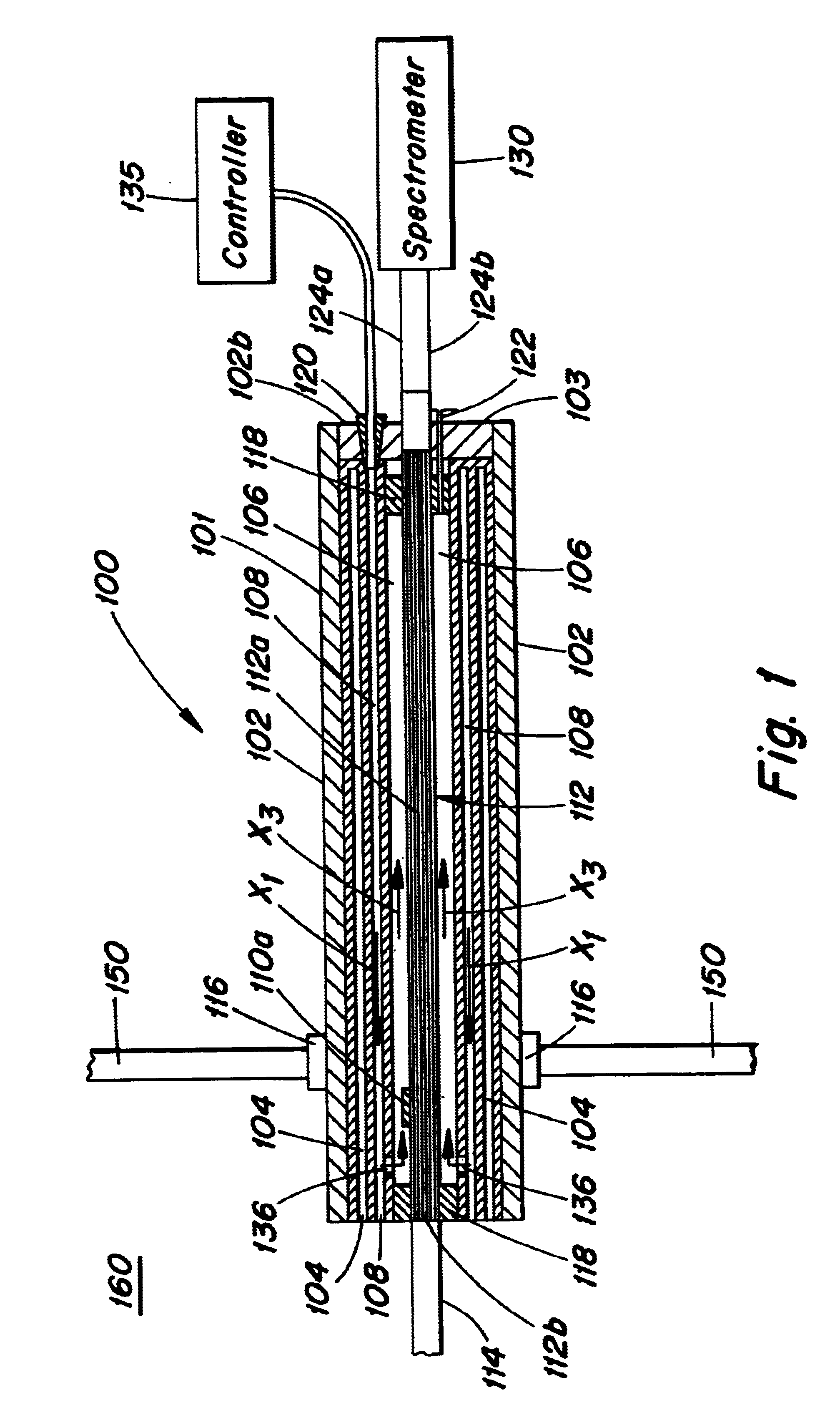
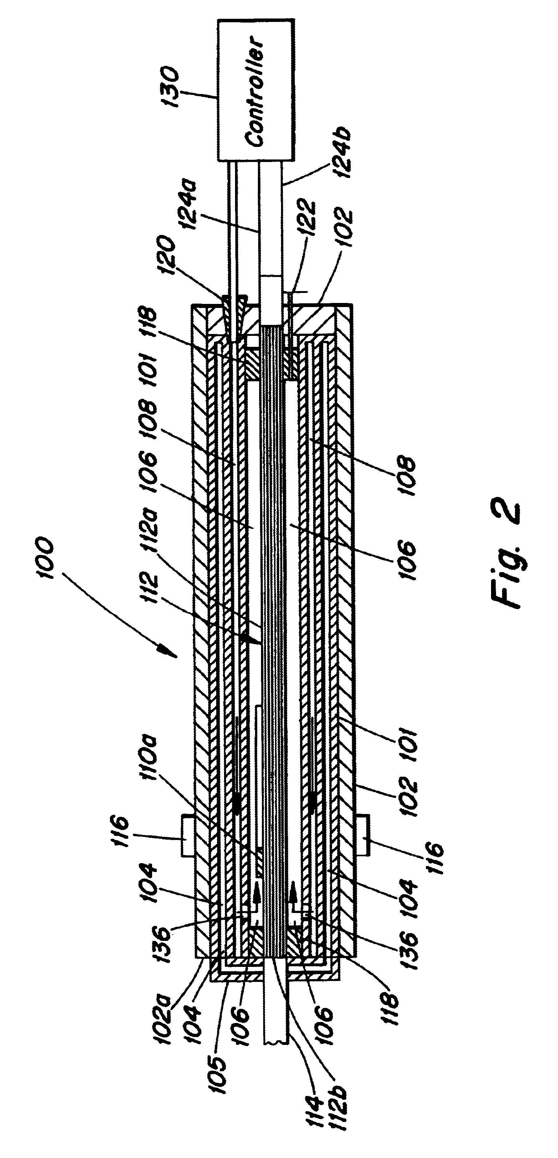
[0018]The present invention provides a gas sensing device for sensing gas levels within a chamber. The gas sensing device includes a housing and a probe disposed within the housing having a tip extending from the housing into the chamber. The probe tip includes a gas sensor disposed thereon for sensing gas levels within the chamber. As will be discussed in greater detail with respect to the accompanying Figures, during operation, the gas sensing device maintains a temperature of the gas sensor via passageways disposed around the probe within the housing of the gas sensing device.

[0019]Now making reference to the Figures, and more particularly FIG. 1, FIG. 1 illustrates a side view of a gas sensing device 100 partially disposed within a chamber 160 in accordance with an embodiment of the present invention. The gas sensing device 100 includes a housing 102, a probe 112 extending through the housing 102 and a sensor 114 disposed at an end 112b of the probe 112. The gas sensing device 1...


PUM

PropertyMeasurementUnit
temperatureaaaaaaaaaa
flammableaaaaaaaaaa
constant temperatureaaaaaaaaaa

Abstract

A gas monitoring device for monitoring gas levels within a chamber is provided. The gas monitoring device includes a housing having a probe with a sensor disposed on the probe. The probe extends through the housing and into a chamber such that the sensor is within the chamber. The housing includes a first passageway disposed about the probe and second passageway disposed about the first passageway. During operation of the gas monitoring device, a temperature adjusting medium enters the second passageway through an inlet of the housing and then enters into the first passageway via the second passageway. As the temperature adjusting medium travels through the first passageway, the temperature adjusting medium adjusts the temperature of the probe. The temperature adjusting medium adjusts the temperature of the probe through thermal conduction. As the temperature of the probe adjusts, the temperature of the sensor also adjusts through thermal conduction.

Description

BACKGROUND OF THE INVENTION[0001]1. Field of the Invention[0002]The present invention relates generally to gas sensing devices. More specifically, the present invention relates to a gas sensing device for measuring oxygen levels in fuel tanks.[0003]2. Description of Related Art[0004]Since 1959, a number of aircraft fuel tanks have unexpectedly exploded. Typically, the explosions occurred when an unknown ignition source ignited the fuel / vapor mixture in the fuel tank. Fuel / vapor mixtures are created during consumption of fuel within the fuel tank by engines of the aircraft. The consumed fuel leaves a space within the tank which generally fills with atmospheric air containing oxygen. The presence of both a flammable gas and the fuel / vapor mixture within the space creates the potential for an explosion within the fuel tank upon ignition. The industry has responded with various methods and apparatuses, as discussed in Air Safety Week, Vol. 15 No. 16, Apr. 16, 2001, “Fatal Explosion High...

Claims


Application Information

Patent Timeline
Patent Type & Authority Patents(United States)
IPC IPC(8): G01N21/77G01N33/00G01N21/64
CPCG01N21/7703G01N33/0016G01N2021/772G01N2021/7786
Inventor SUSKO, KENNETH
Owner SUSKO KENNETH
Why Eureka
Try Eureka