Two-step roller finger cam follower having angled lock pin

a follower and roller finger technology, applied in the direction of valve arrangements, machines/engines, mechanical equipment, etc., can solve the problems of unfavorable follower movement, unfavorable follower movement, and unfavorable follower movement, so as to reduce the diameter and length of the latch pin, and eliminate the moment of bending the latch pin

Active Publication Date: 2005-08-09
DELPHI TECH IP LTD
View PDF4 Cites 49 Cited by
  • Summary
  • Abstract
  • Description
  • Claims
  • Application Information

AI Technical Summary

Benefits of technology

[0014]The latch pin channel is formed in the follower body at an angle to the pivot pin axis (and hence to a radius of motion of the slider tip) of less than 180° such that the latch pin engages the slider tip non-orthogonally, which allows the force of the slider tip to be borne directly by a wall of the canted channel, thus eliminating any bending moment in the latch pin and permitting a reduction in latch pin diameter and length. The angle further prevents the latch pin from inadvertently engaging the slider tip when the slider is in full lost-motion position.

Problems solved by technology

A drawback of this prior art roller finger follower is that the axis of the locking pin intersects the axis of the pivot pin for the slider; i.e., the motion of the locking pin is along an extension of a pivot pin and slider tip radius.
Providing acceptable support for such bending moment requires that the locking pin have a relatively long bore and large diameter, thus increasing undesirably the size of the follower body and hence the overall follower assembly.
A further drawback of such a roller finger follower is that the locking pin can inadvertently engage the wrong side of the slider tip if the locking pin is commanded to move when the slider is fully depressed by the cam lobe, causing the follower to become locked in the full lost-motion position, which condition is highly undesirable.

Method used


Image

  • Two-step roller finger cam follower having angled lock pin
  • Two-step roller finger cam follower having angled lock pin
  • Two-step roller finger cam follower having angled lock pin

Examples


Embodiment Construction

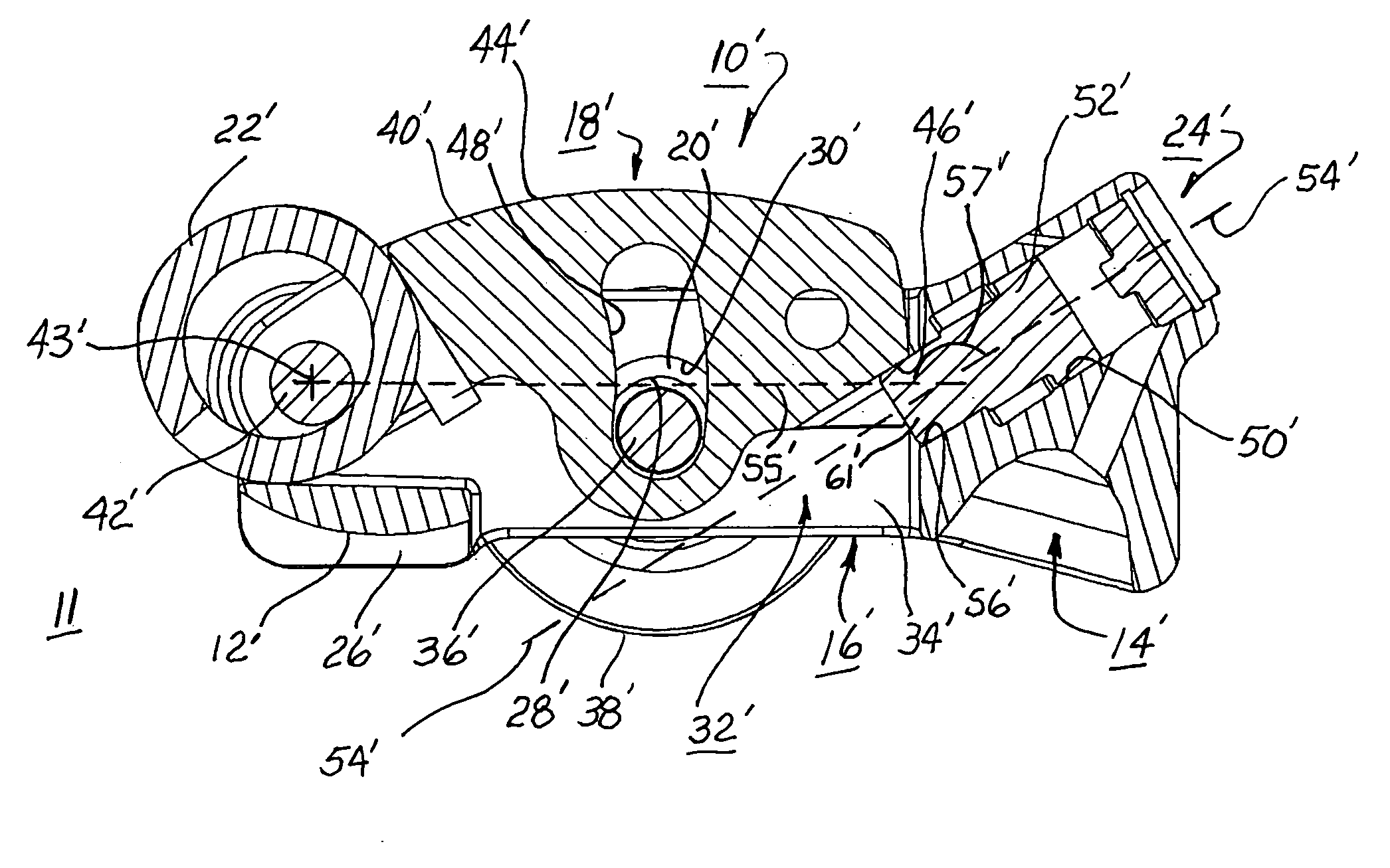
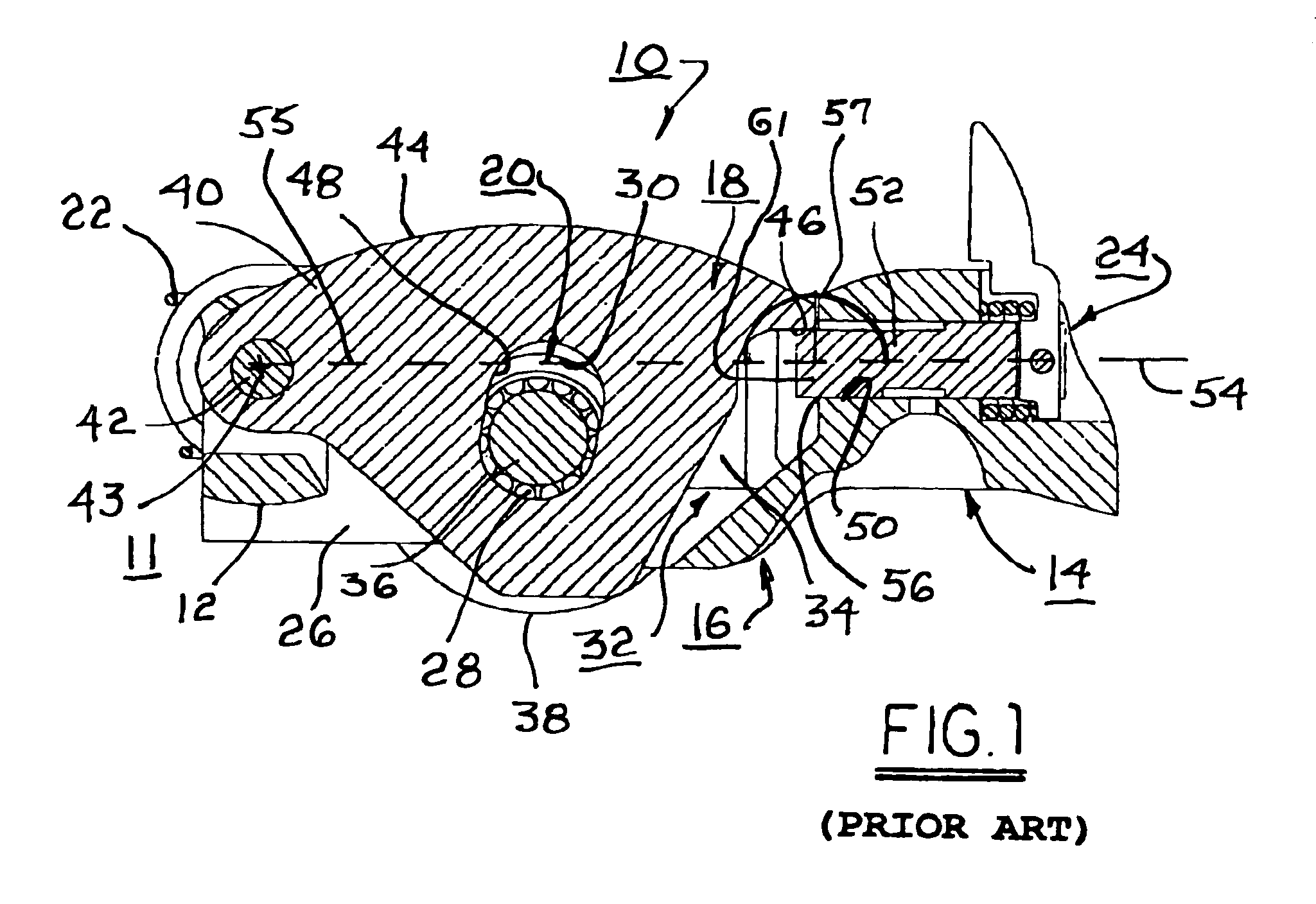
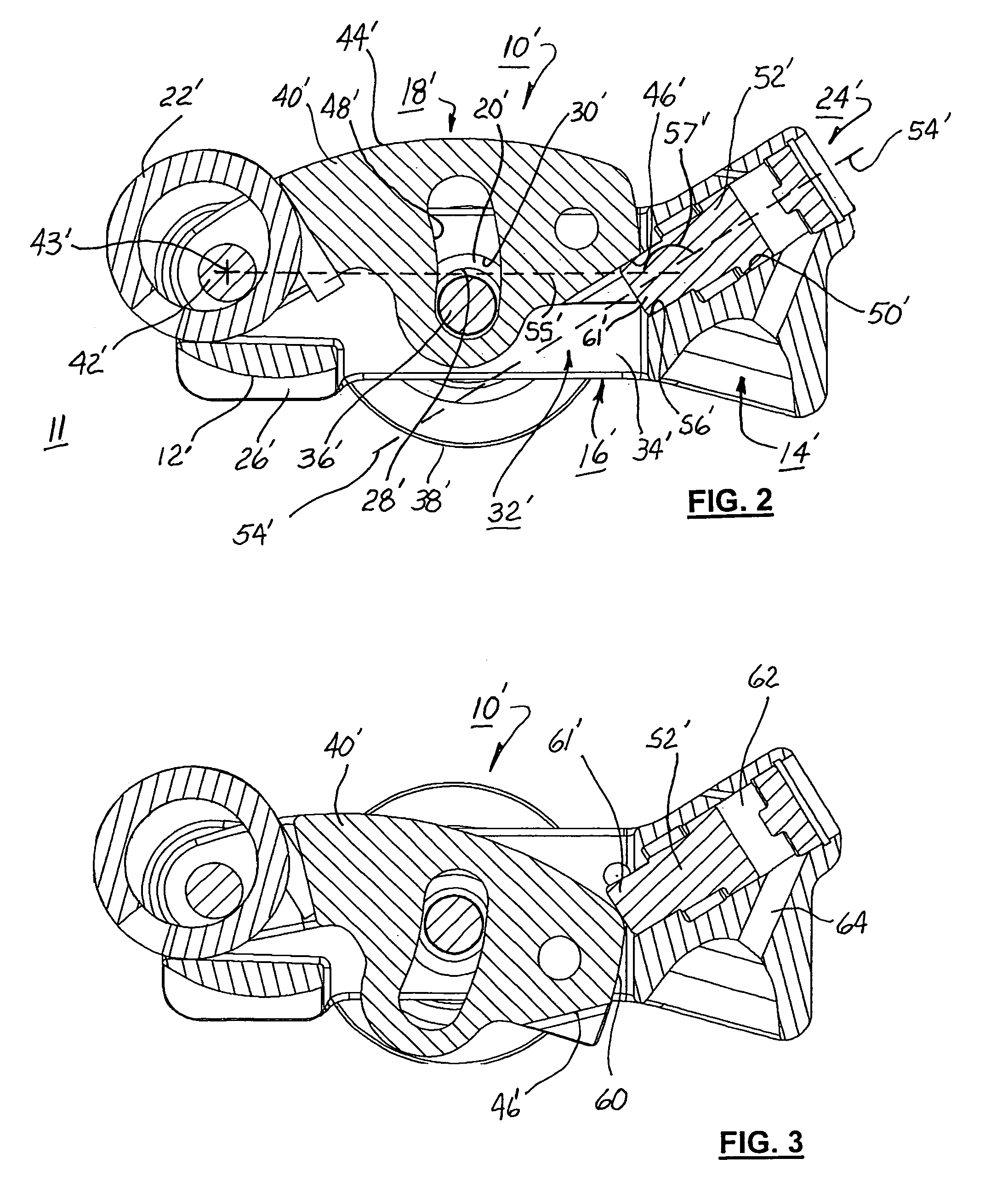
[0019]Referring to FIGS. 1 through 3, prior art RFF 10 and improved RFF 10′ are shown. Prior art RFF 10 is configured substantially as shown in incorporated U.S. Pat. No. 6,755,167, the details of which need not be repeated here. Sufficient detail, however, is provided to appreciate the improvement and benefit afforded by improved RFF 10′ in accordance with the invention.

[0020]A roller finger follower such as RFF 10 or RFF 10′ is intended for use with an internal combustion engine 11 comprising a camshaft configuration (shown in reference) having a central high-lift lobe flanked by a pair of low-lift lobes. The high lift lobe is either enabled, by latching of a central slider within the RFF, or disabled, by unlatching the central slider and allowing it to pivotably follow the high-lift lobe in lost motion.

[0021]As FIGS. 1 through 3 show RFF 10 and RFF 10′ in longitudinal cross-section, some components and aspects are not shown, particularly those that are paired in the actual embodi...


PUM


Abstract

A two-step roller finger follower for shifting between high-lift and low-lift valve modes includes a body having side members defining coaxially disposed shaft orifices, a pallet end, a socket end, a slider arm aperture, and a latch pin channel. The socket end is mountable to a lash adjuster, and the pallet end is matable with a valve stem. A slider arm for engaging a high-lift cam lobe is disposed in the aperture, is pivotably mounted to the body, and includes a slider tip for engaging a latch pin having a nose section. A spool-shaped roller is adapted to follow the surface motion of low-lift cam lobes. The axis of the latch pin intersects a radius extension of the slider arm at an angle of less than 180° such that the latch pin is prevented from accidentally locking the slider arm in its lost-motion position.

Description

TECHNICAL FIELD[0001]The present invention relates to roller finger followers used for variable valve actuation in overhead cam type internal combustion engines, and more particularly to a roller finger follower wherein a locking pin is disposed at an angle to a radius of rotation of a slider arm pivotably mounted in a follower body.BACKGROUND OF THE INVENTION[0002]Roller Finger Followers (RFF) are widely used in overhead cam internal combustion engines to sequentially open and close the cylinder intake and exhaust valves. In a typical application, the RFF serves to transfer and translate rotary motion of a cam shaft lobe into a pivotal motion of the RFF to thereby open and close an associated valve.[0003]It is known that, for a portion of the duty cycle of a typical multiple-cylinder engine, the performance load can be met by a functionally smaller engine having fewer firing cylinders, and that at low-demand times fuel efficiency can be improved if one or more cylinders of a larger...

Claims


Application Information

Patent Timeline
Patent Type & Authority Patents(United States)
IPC IPC(8): F01L1/18F01L13/00
CPCF01L1/18F01L1/182F01L1/185F01L13/0036F01L2105/02F01L2001/186F01L2305/02
Inventor GERZSENY, JOSEPH C.LIPINSKI, ANDREW J.
Owner DELPHI TECH IP LTD
Why Eureka
Try Eureka