Shielded connector of reduced-size with improved retention characteristics

a technology of shielding connectors and connectors, applied in the direction of coupling device connections, coupling protective earth/shielding arrangements, electrical devices, etc., can solve the problems of high manufacturing cost of shielding connectors, difficulty in achieving miniaturization goals, and insufficient dimensional stability of shielding sleeve portions b>307/b>, so as to reduce size and weight, improve retention characteristics, and reduce the effect of size and weigh

Inactive Publication Date: 2005-08-09
MOLEX INC
View PDF4 Cites 33 Cited by
  • Summary
  • Abstract
  • Description
  • Claims
  • Application Information

AI Technical Summary

Benefits of technology

[0013]It is therefore a general object of the present invention is to provide a shielded connector that is reduced in size and in weight, particularly on the receptacle side of the connector, and which is further durable suitable for repeated use in insertion and rem

Problems solved by technology

However, in the prior art connectors described above and shown in FIGS. 15 & 16, there is a problem.
The manufacturing cost of these connectors is high because the engagement sleeve portion 307 is formed by drawing.
The outer profile of these connectors is also increased because of this drawn structure, resulting in difficulty in achieving the goal of miniaturization.
The engagement sleeve portion 307 is formed by drawing so that there is a problem that the sleeve portion 307 does not have satisfactory dimensional stability.
Furthermore, a large force, such as a twisting force, may be applied to the engagement sleeve portion 307 when engaged with the plug connector P. The forces generated by repeated removal and insertion may weaken the drawn portions of the connector.
In the aforementioned conventional connectors, although the housing has structure supports the metal shield and has a desired mechanical strength, it has an unnecessarily large thickness for its structural stability.
This creates a problem that inhibits the goal of attaining further miniaturization and weight reduction.
Additionally, in this type of connector where repeated removal and insertion of the plug connector P to the receptacle connector R occurs, frictional wear or deformation can occur with the drawn engagement portions, so that there is a fear that

Method used


Image

  • Shielded connector of reduced-size with improved retention characteristics
  • Shielded connector of reduced-size with improved retention characteristics
  • Shielded connector of reduced-size with improved retention characteristics

Examples


Embodiment Construction

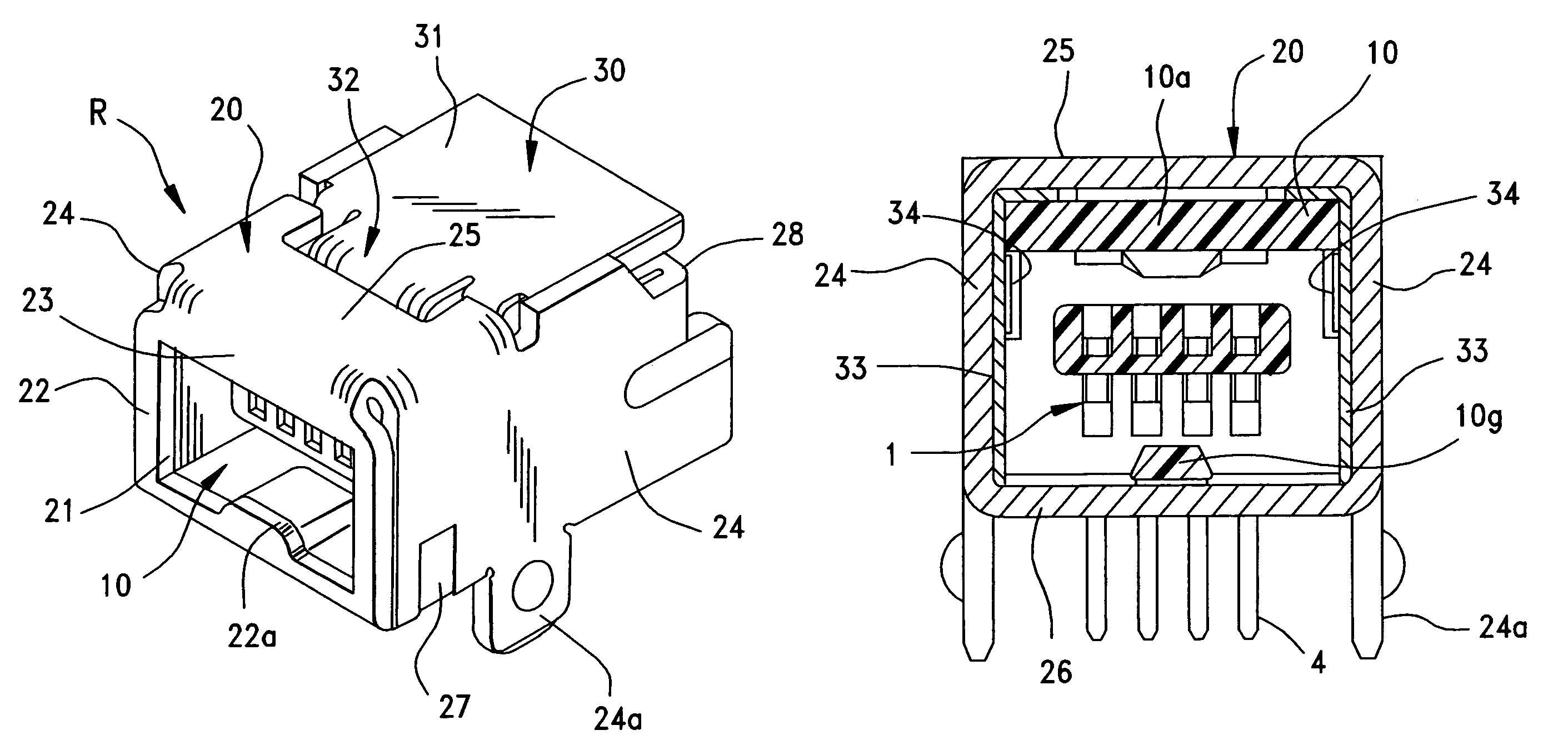
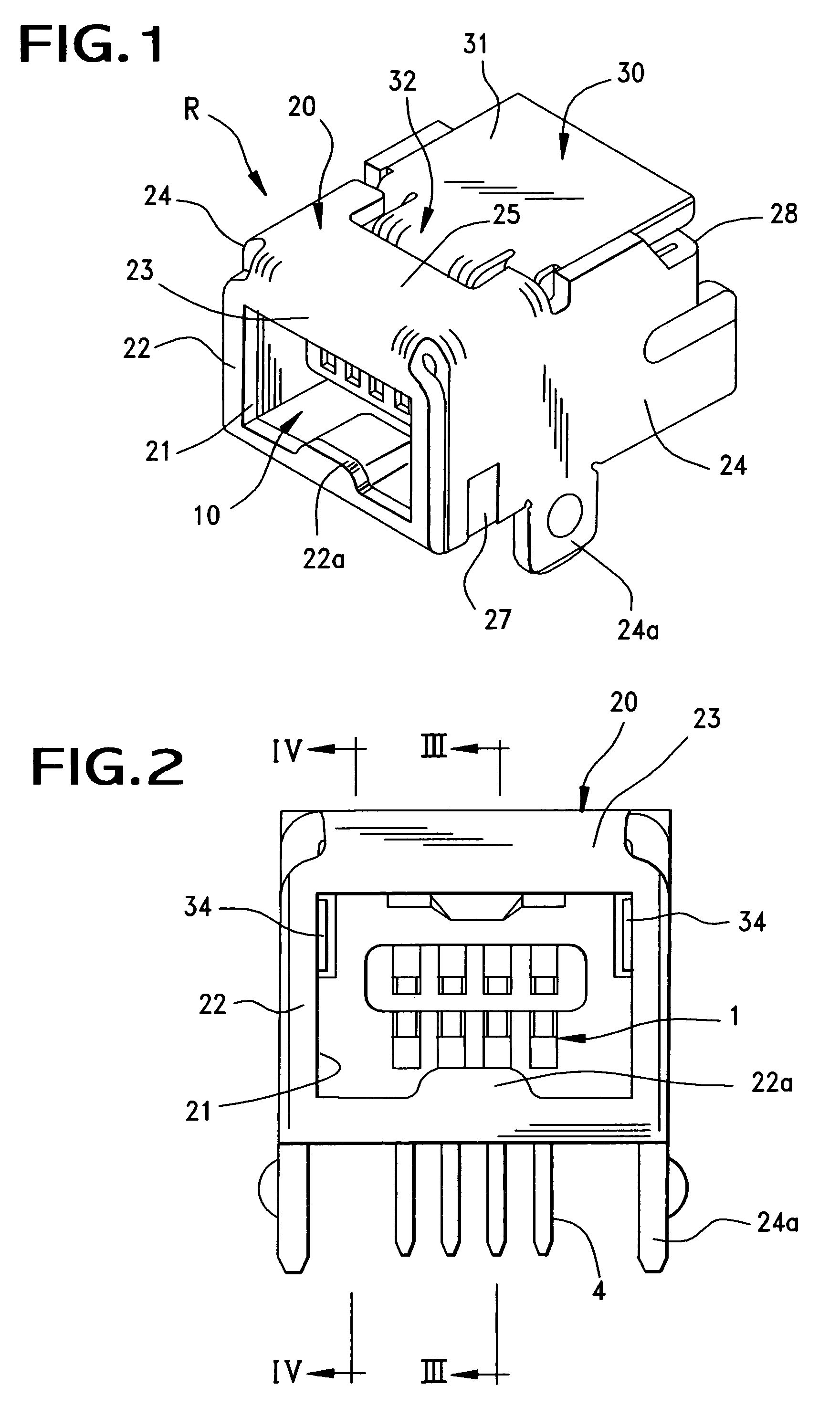
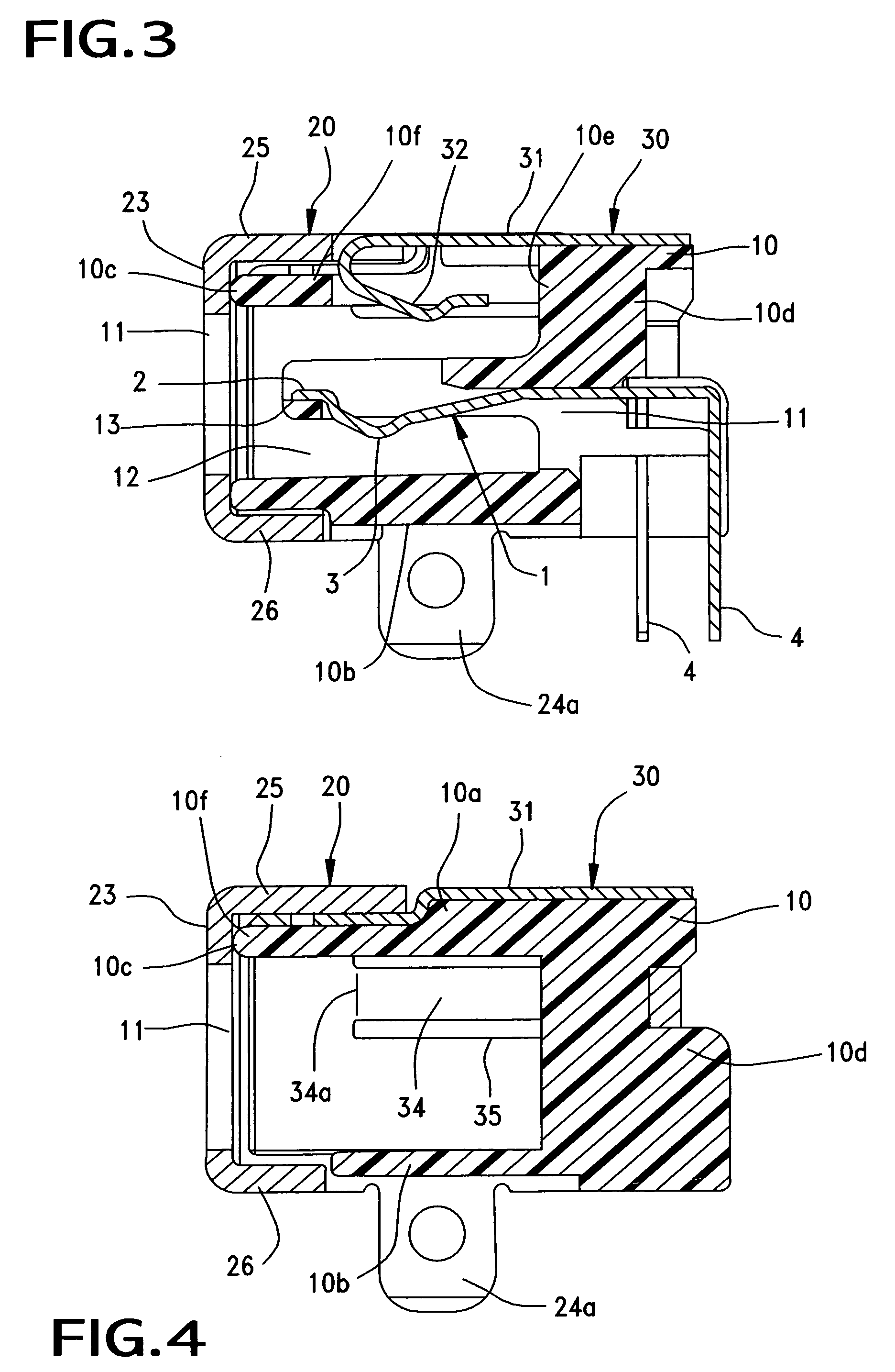
[0040]An improved shielded connector R constructed in accordance with the principles of the present invention is illustrated in FIGS. 1–14 and in the embodiment shown, a “DIP” (Dual-In-line Process) type electrical connector of USB (Universal Serial Bus) style is illustrated as an example of a connector to which the principles of the present invention may be applied. The connector shown is one that is intended to be mounted on a substrate, such as a circuit board (not shown). As illustrated in FIGS. 1–3, the shielded connector R is provided with an inner insulated housing for supporting one or more conductive terminals or contacts 1, and a metal shell 20 for overlying the outer surface of the connector housing to thereby shield the terminal 1. The metal shell 20 includes a front frame panel portion 22 that defines an opening 21 in the shell 20 and the connector R. This opening 21 receives a portion of an opposing plug connector P, such as the one shown in FIG. 16. The front frame po...


PUM


Abstract

A reduced weight and size shielded receptacle connector includes an internal insulative connector housing having top and bottom walls, without any sidewalls interconnecting the top and bottom walls together. A plurality of conductive terminals are supported within the connector. A receptacle portion of the connector is formed in cooperation with the top and bottom walls of the connector housing and with a pair of metal sidewalls formed by bending a shield member around parts of the connector housing. A metal retaining shield is provided that also overlies a portion of the connector housing and which is partially retained on the connector housing by the metal shell. The shield not only provides shielding, but also serves to retain the opposing connector in mating engagement with receptacle connector by way of three retention members that extend in and engaged the opposing connector in three different directions.

Description

BACKGROUND OF THE INVENTION[0001]The present invention relates generally to shielded connectors, and more particularly to small-sized connectors having improved opposing connector retention characteristics.[0002]It is known that metal shields may be disposed on the exterior circumferential surface of box-shaped insulative housings of connectors for the purposes of preventing interference, such as electrical noise. One example of such a connector is disclosed in Japanese Utility Model Application Laid-Open No. Hei 5-34679, Japanese Patent Application Laid-Open No. Hei 10-83866, and others. The connector disclosed in these publications is one that is mounted to a substrate such as a printed circuit board and is formed so that a pair of substantially U-shaped shield members made of metal plates are overlapped on four or three surfaces of the exterior of a substantially box-shaped insulative connector housing.[0003]FIGS. 15 and 16 of this application show such a conventional shielded co...

Claims


Application Information

Patent Timeline
IPC IPC(8): H01R13/658H01R13/648H01R12/70H01R13/6582
CPCH01R12/7064H01R13/6582H01R13/6587
Inventor YAMAGUCHI, TOMISABUROTETSUYA, ASAKAWA
Owner MOLEX INC
Why Eureka
Try Eureka