Fuel cell stack

a fuel cell and stack technology, applied in the field of fuel cell stacks, can solve the problems of low power generation performance of the fuel cell b>a /i>positioned on the outlet side, and the simple device of the fuel cell, and achieve the effect of maintaining the power generation performance of the overall fuel cell stack and simple structur

Inactive Publication Date: 2005-08-09
HONDA MOTOR CO LTD
View PDF7 Cites 27 Cited by
  • Summary
  • Abstract
  • Description
  • Claims
  • Application Information

AI Technical Summary

Benefits of technology

[0013]A main object of the present invention is to provide a fuel cell stack having a simple structure in which the power generation performance is uniform in each of fuel cells stacked to form the fuel cell stack, and the power generation performance of the overall fuel cell stack is maintained desirably.

Problems solved by technology

Therefore, the fuel cell device is not simple, and economical.
In particular, when many fuel cells 3a are stacked in a vehicle application, the power generation performance of the fuel cells 3a positioned on the outlet side is considerably low.

Method used


Image

  • Fuel cell stack
  • Fuel cell stack
  • Fuel cell stack

Examples


Embodiment Construction

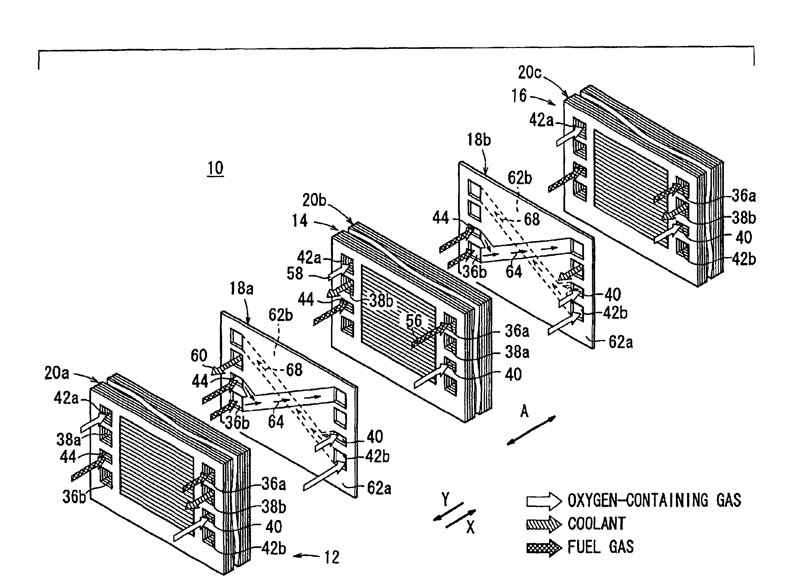
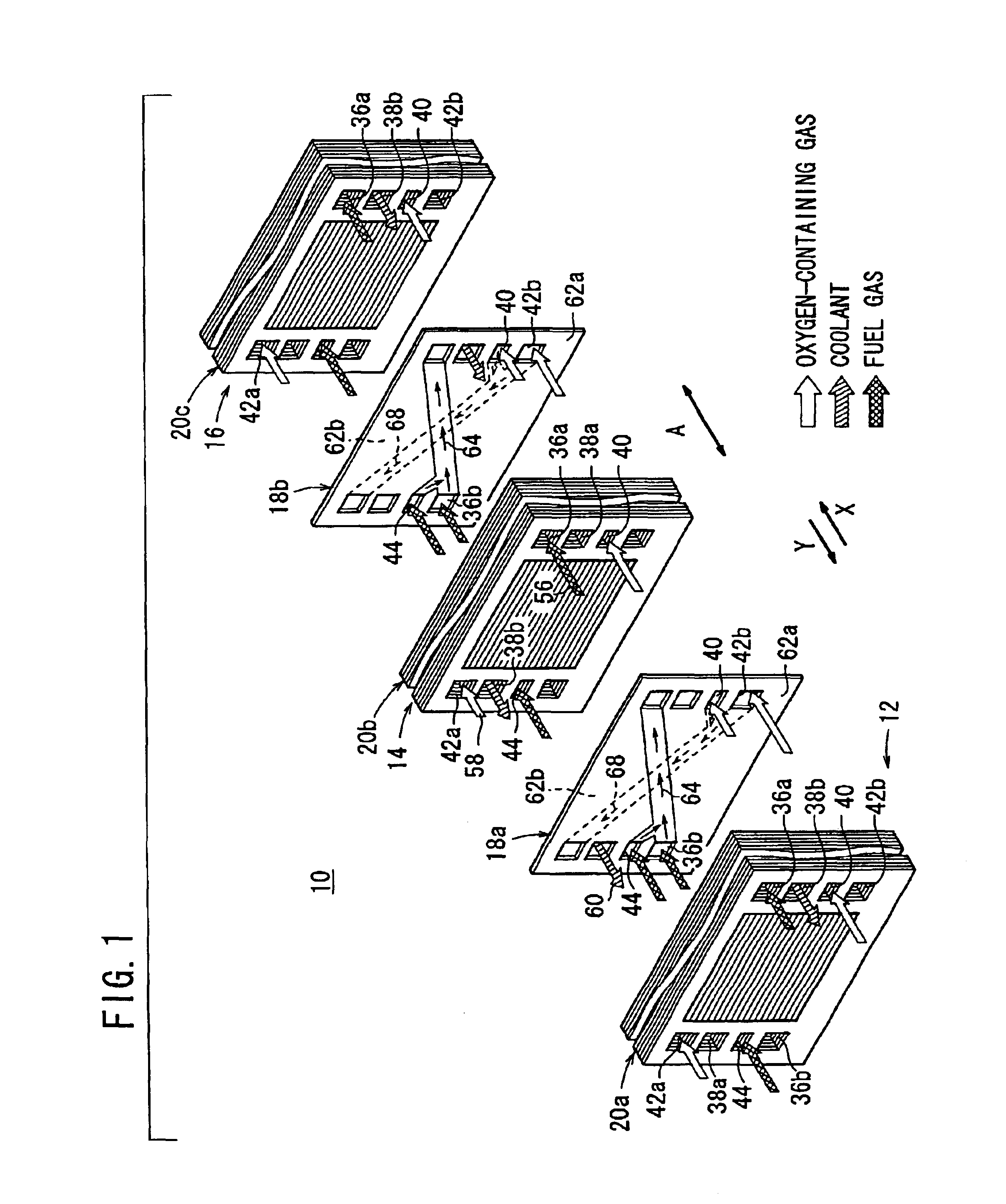
[0027]FIG. 1 is an exploded view schematically showing a fuel cell stack 10 according to an embodiment of the present invention.

[0028]The fuel cell stack 10 includes a first fuel cell module 12, a second fuel cell module 14, and a third fuel cell module 16 aligned in a direction indicated by an arrow X. Reactant gases such as an oxygen gas and a fuel gas are supplied in the direction indicated by the arrow X. An intermediate plate 18a is interposed between the first fuel cell module 12 and the second fuel cell module 14. An intermediate plate 18b is interposed between the second fuel cell module 14 and the third fuel cell module 16.

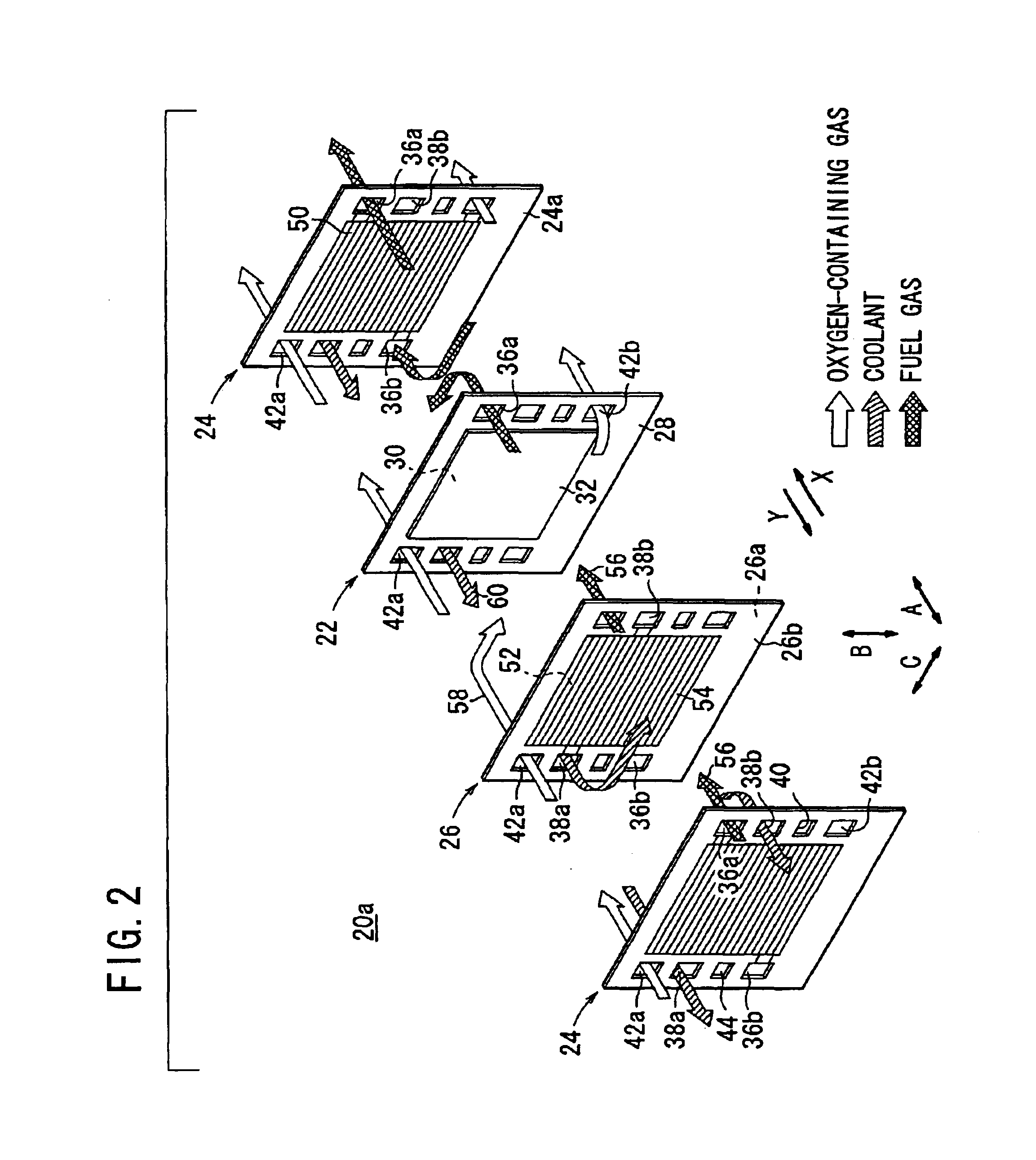
[0029]The first fuel cell module 12, the second fuel cell module 14, and the third fuel cell module 16 have substantially the same structure. Each of the first through third fuel cell modules 12, 14, 16 includes a certain number of unit cells 20a, 20b, 20c stacked in a direction indicated by an arrow A. As shown in FIG. 2, the unit cell 20a includes a fir...


PUM

PropertyMeasurementUnit
chemicalaaaaaaaaaa
DC electric currentaaaaaaaaaa
poweraaaaaaaaaa

Abstract

A fuel gas passage, an oxygen-containing gas passage, and a coolant passage extend through a fuel cell stack. Each of the fuel gas passage and the oxygen-containing gas passage is formed by serially connecting passages between the first through third fuel cell modules. The fuel gas flows through the fuel gas passage, and the oxygen-containing gas flows through the oxygen-containing gas passage from the first fuel cell module toward the third fuel cell module. The coolant passage is formed by serially connecting passages between the first through third fuel modules. The coolant flows through the coolant passage from the third fuel cell module toward the first fuel cell module. The direction of the flow of the coolant is opposite to the direction of the flows of the fuel gas and the oxygen-containing gas.

Description

BACKGROUND OF THE INVENTION[0001]1. Field of the Invention[0002]The present invention relates to a fuel cell stack formed by connecting a plurality of fuel cell modules together. Each of the fuel cell modules includes units of fuel cells, i.e., the fuel cell module is formed by stacking a plurality of membrane electrode assemblies and separators alternately. The Each of the membrane electrode assemblies includes an anode, a cathode, and an electrolyte membrane interposed between the anode and the cathode.[0003]2. Description of the Related Art[0004]For example, a solid polymer electrolyte fuel cell employs a membrane electrode assembly (MEA) which includes two electrodes (anode and cathode) and an electrolyte membrane interposed between the electrodes. The electrolyte membrane is a polymer ion exchange membrane (proton exchange membrane). Each of the electrodes comprises a catalyst and a porous carbon sheet. The membrane electrode assembly is interposed between separators (bipolar p...

Claims


Application Information

Patent Timeline
Patent Type & Authority Patents(United States)
IPC IPC(8): H01M8/24H01M8/12H01M8/10H01M8/02H01M8/04
CPCH01M8/0258H01M8/04014H01M8/04089H01M8/24Y02E60/50H01M8/0267H01M8/241H01M8/2483
Inventor WARIISHI, YOSHINORIKIKUCHI, HIDEAKISUZUKI, MASAHARUODA, MASARUFUJII, YOSUKEBABA, ICHIRO
Owner HONDA MOTOR CO LTD
Why Eureka
Try Eureka