
Cooling electromagnetic stirrers

a technology of electromagnetic stirrers and cooling systems, which is applied in the field of electromagnetic stirrer cooling systems, can solve the problems of increasing the capital and operating costs and reducing the efficiency of electromagnetic stirring systems

Inactive Publication Date: 2005-08-09
ABB INC
View PDF10 Cites 18 Cited by
  • Summary
  • Abstract
  • Description
  • Claims
  • Application Information

AI Technical Summary

Benefits of technology

[0010]In order to overcome the disadvantages of water-cooling systems used with electromagnetic stirrers, it has been found, in accordance with the present invention, that cooling efficiency and operating performance of electromagnetic stirrers can be improved by the use of magnetic fluid as a cooling and insulating medium.

Problems solved by technology

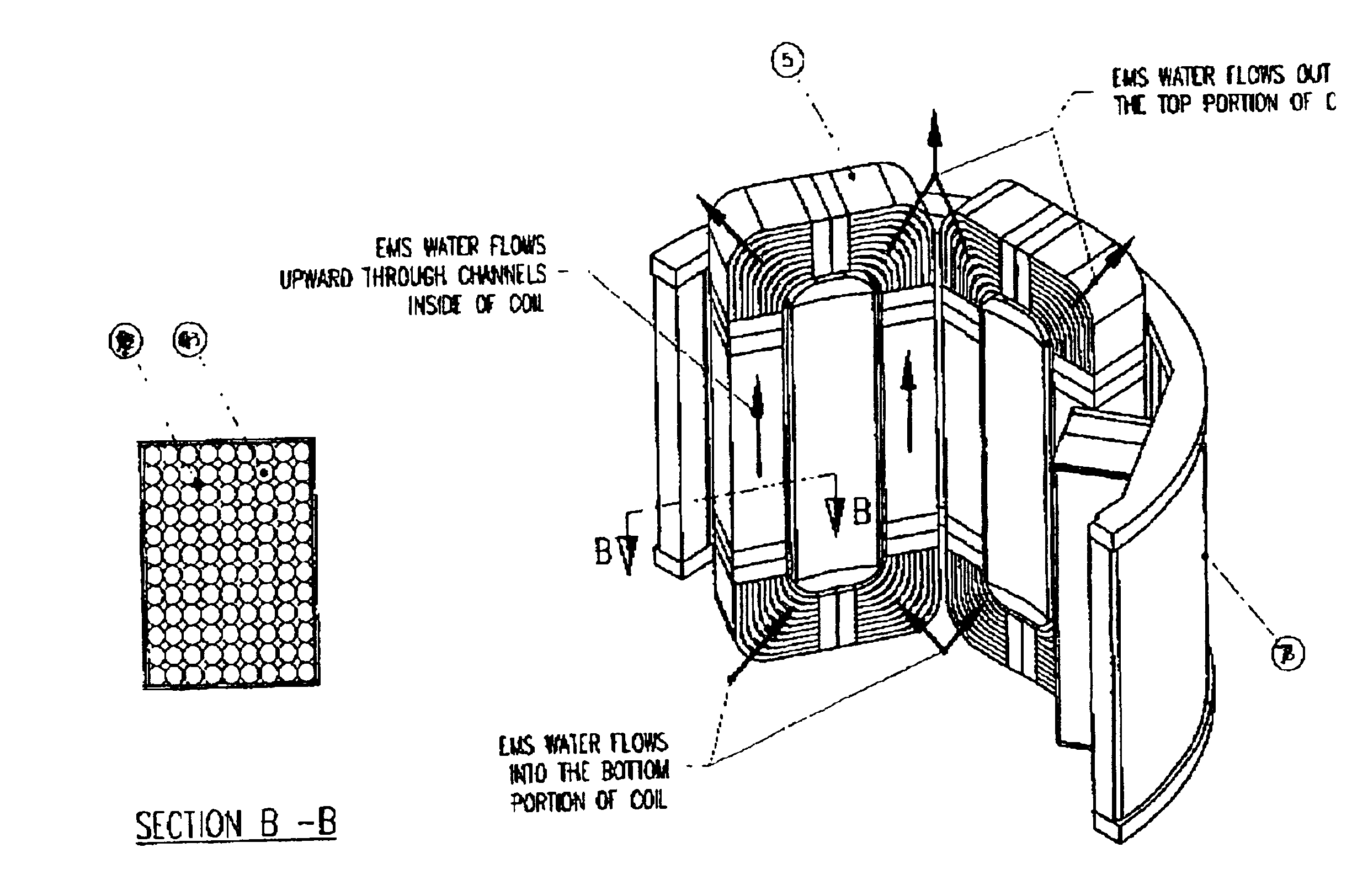
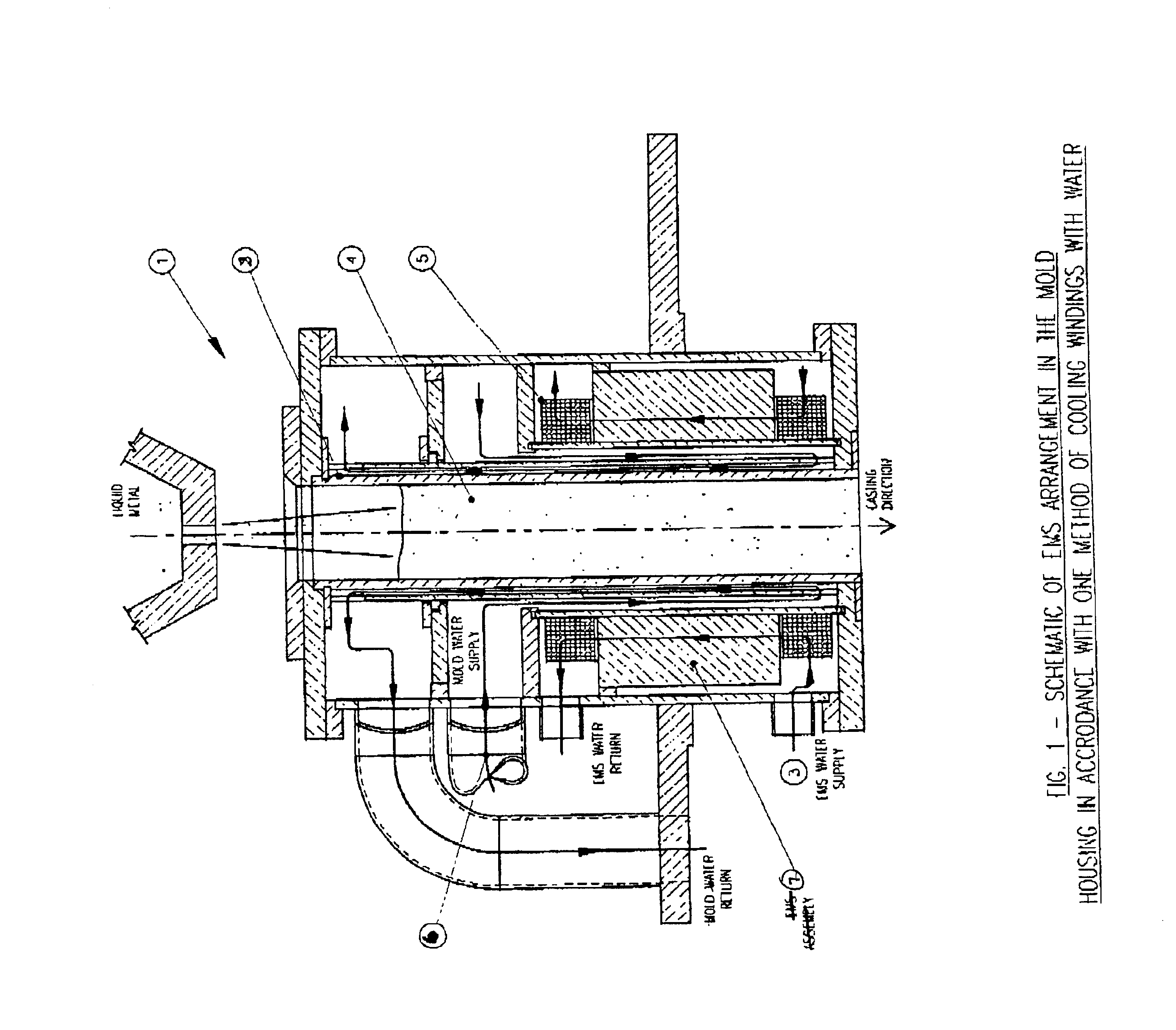
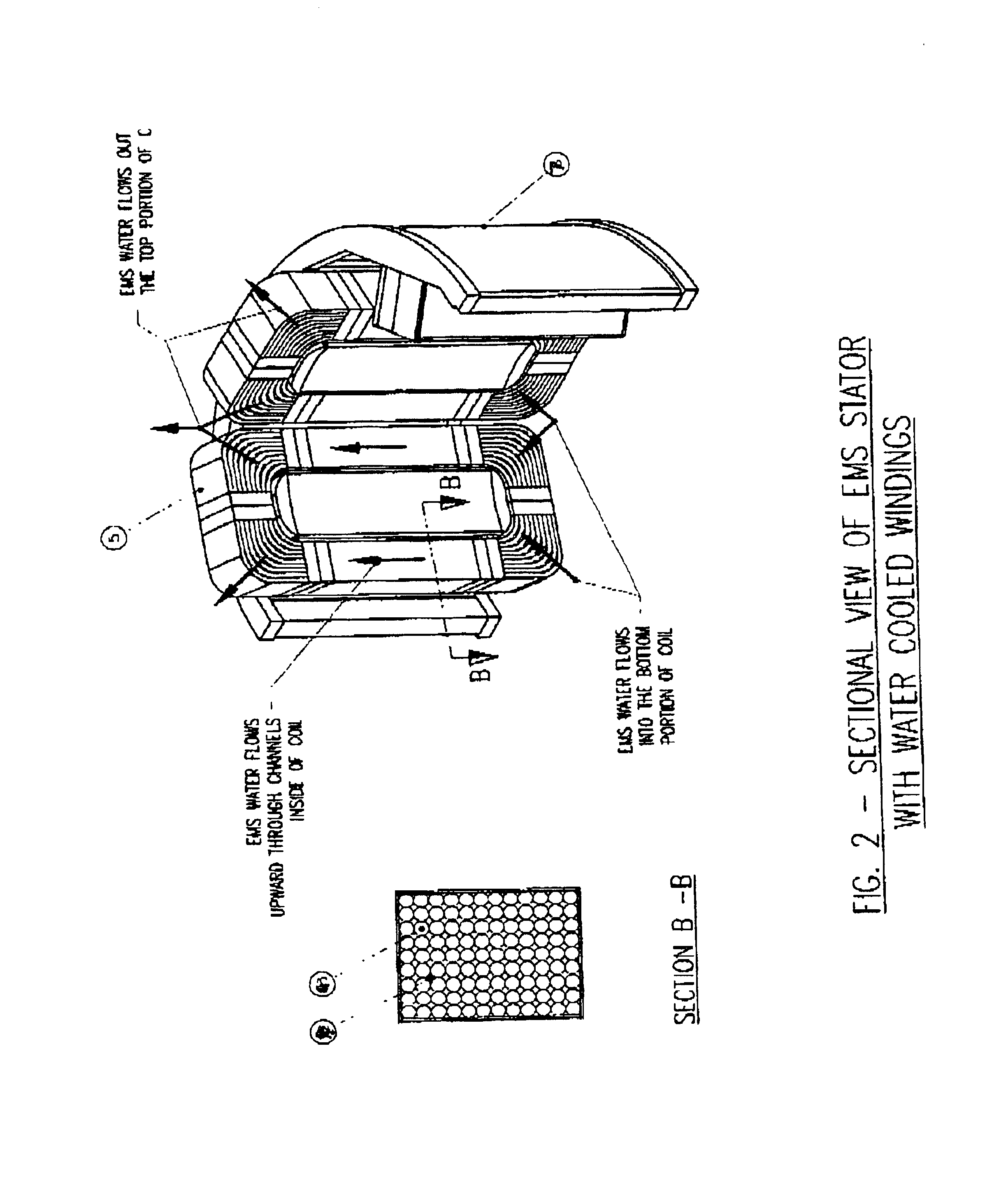
Because untreated water has rather high electrical conductivity, the water needs to be chemically treated to reduce the electrical conductivity to acceptable levels and / or the wire insulation is reinforced in order to eliminate any microscopic pores in the insulation to avoid a possibility of direct contact between the copper wire and water, which leads to copper erosion and eventual failure of the device.
Moreover, both reliable wire insulation and a voltage limitation are required in order to prevent short circuiting between the rather tightly packaged windings, as the cooling water, even with a reduced electrical conductivity, is a poor insulating medium.
The above noted water-cooling systems for external or internal cooled windings comprise of a closed circuit water supply equipped with pumps, filters, instrumentation, etc. which adds to capital and operating costs of electromagnetic stirring systems.
In spite of these prior art disclosures, electromagnetic stirrers employed in the metals processing industries, and continuous casting of steel in particular, remain water-cooled, except for stirrers with a very limited power input which may be air-cooled.
This dependence can be, and often is compromised by defects in stirrer fabrication, materials used, equipment malfunction or human error.

Method used


Image

  • Cooling electromagnetic stirrers
  • Cooling electromagnetic stirrers
  • Cooling electromagnetic stirrers

Examples


embodiment

[0051 No. 1

[0052]In order to determine temperature within the windings at different current inputs and ferrofluid magnetizations, fifteen thermocouples were embedded into one winding as shown in FIG. 8. There were three sets of five thermocouples, each set having one thermocouple in the center of a cross-section and four in the middle of its sides. The winding cross-sections were selected as follows: one in the mid-height of the vertical portion, i.e. section A—A, and one each in the bottom and the top horizontal portions of the windings, as indicated respectively by sections C—C and B—B in FIG. 8.

[0053]FIG. 9 shows the temperatures obtained in the vertical portion of the winding, i.e. section A—A, at different current inputs and magnetizations of ferrofluid. As seen from FIG. 9, with a magnetization of 150 and 200 Gauss, the winding temperature reached 200° C. at 200 Amperes. In this embodiment, similar to the practice of cooling windings with water, the wire has a multi-layer insu...


PUM

PropertyMeasurementUnit
Temperatureaaaaaaaaaa
Angleaaaaaaaaaa
Electrical resistivityaaaaaaaaaa

Abstract

Cooling of the electrical coils of an electromagnetic stirrer is effected using a ferrofluid.

Description

FIELD OF INVENTION[0001]The present invention relates to generally to electromagnetic devices producing magnetic fields with a significant spatial gradient, and more specifically to cooling systems of electromagnetic stirrers employed for stirring liquid metals.BACKGROUND TO THE INVENTION[0002]Universally, the windings of electromagnetic devices of comparatively large power input are cooled with fluids, such as oils or water, which remove the heat evolving in the windings due to ohmic losses. The mechanism of heat removal from the windings of such devices is based on either thermal convection or forced fluid flow. The latter approach has been used for cooling of electromagnetic stirrers, (abbreviated herein as EMS), widely used in metals processing industries. These stirrers are cooled by water supplied under pressure either from a dedicated source or for cooling of a casting mold.[0003]In accordance with the most commonly used method, the cooling water flow fills in a space volume ...

Claims


Application Information

Patent Timeline
IPC IPC(8): B22D11/11B22D11/115F27D27/00
CPCB22D11/115B22D11/11
Inventor BEITELMAN, LEONIDSEGAL, VLADIMIRCURRAN, CHRISTOPHER P.
Owner ABB INC
Learn More