Membrane probing system with local contact scrub

Inactive Publication Date: 2005-08-09
CASCADE MICROTECH
View PDF108 Cites 11 Cited by
  • Summary
  • Abstract
  • Description
  • Claims
  • Application Information

AI Technical Summary

Benefits of technology

[0018]A probing assembly system for probing an electrical device in accordance with the present invention provides a forward support of incompressible material, a flexible membrane assembly mounted with its central region overlying the support, a plurality of rigid contacts disposed on the membrane assembly within the central region each including a beam and a contacting portion, each contacting portion being arranged in suitable position for pressing engagement with a corresponding pad on the device, each beam being electrically connected to a corresponding flexible conductor that extends into the central region. In accordance with the present invention, the probing assembly further provides a pressure control mechanism including an elastomeric member interposed between each contact and the support and a motion control mechanism locally operating in respect to each contact to urge each beam, when the corresponding contacting portion is placed into pressing engagement with the respective pad, into tilting motion so that different portions of each beam move different distances relative to the forward support and so that each contact is driven, in accordance with this tilting motion, into a lateral scrubbing movement across the corresponding pad. The elastomeric member is positioned so as to resiliently oppose the tilting motion and so as to enable each contact to recover from this tilting motion in a manner avoiding mechanical straining of each beam.
[0019]In accordance with the foregoing system, a high-density arrangement of contacts can be provided o

Problems solved by technology

The elastomeric member further serves as a reliable mechanism for enabling the beam of each rigid contact to recover after tilting thereby avoiding the need to rely on the type of elastic recovery provided by mechanica

Method used


Image

  • Membrane probing system with local contact scrub
  • Membrane probing system with local contact scrub
  • Membrane probing system with local contact scrub

Examples


Embodiment Construction

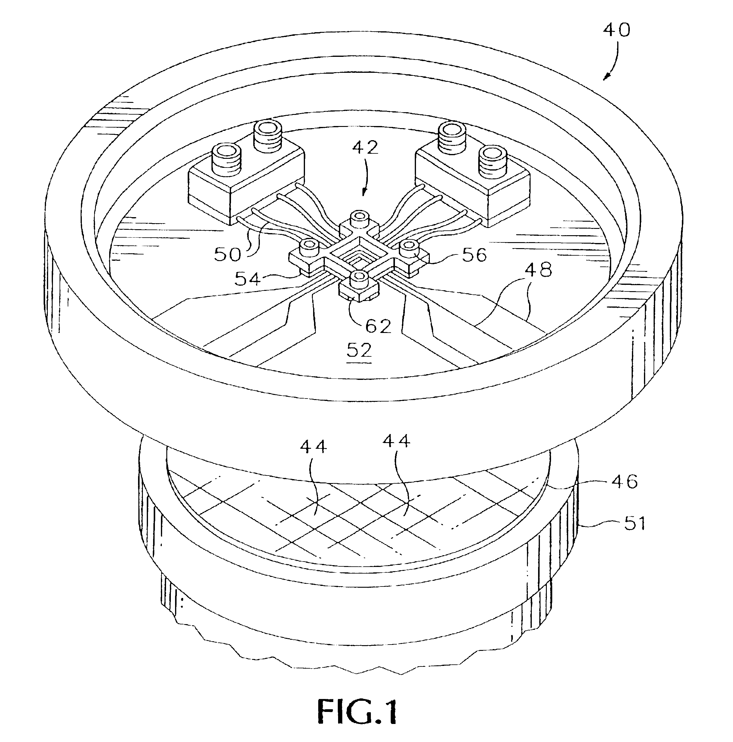
[0035]FIG. 1 shows a probe head 40 for mounting a membrane probing assembly 42 constructed in accordance with the present invention. In order to measure the electrical performance of a particular die area 44 included on the silicon wafer 46, the high-speed digital lines 48 and / or shielded transmission lines 50 of the probe head are connected to the input / output ports of the test instrumentation by a suitable cable assembly, and the chuck 51 which supports the wafer is moved in mutually perpendicular X,Y,Z directions in order to bring the pads of the die area into pressing engagement with the contacts included on the lower contacting portion of the membrane probing assembly.

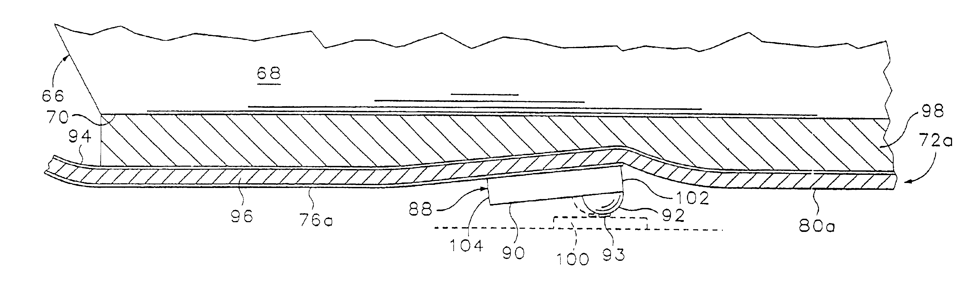
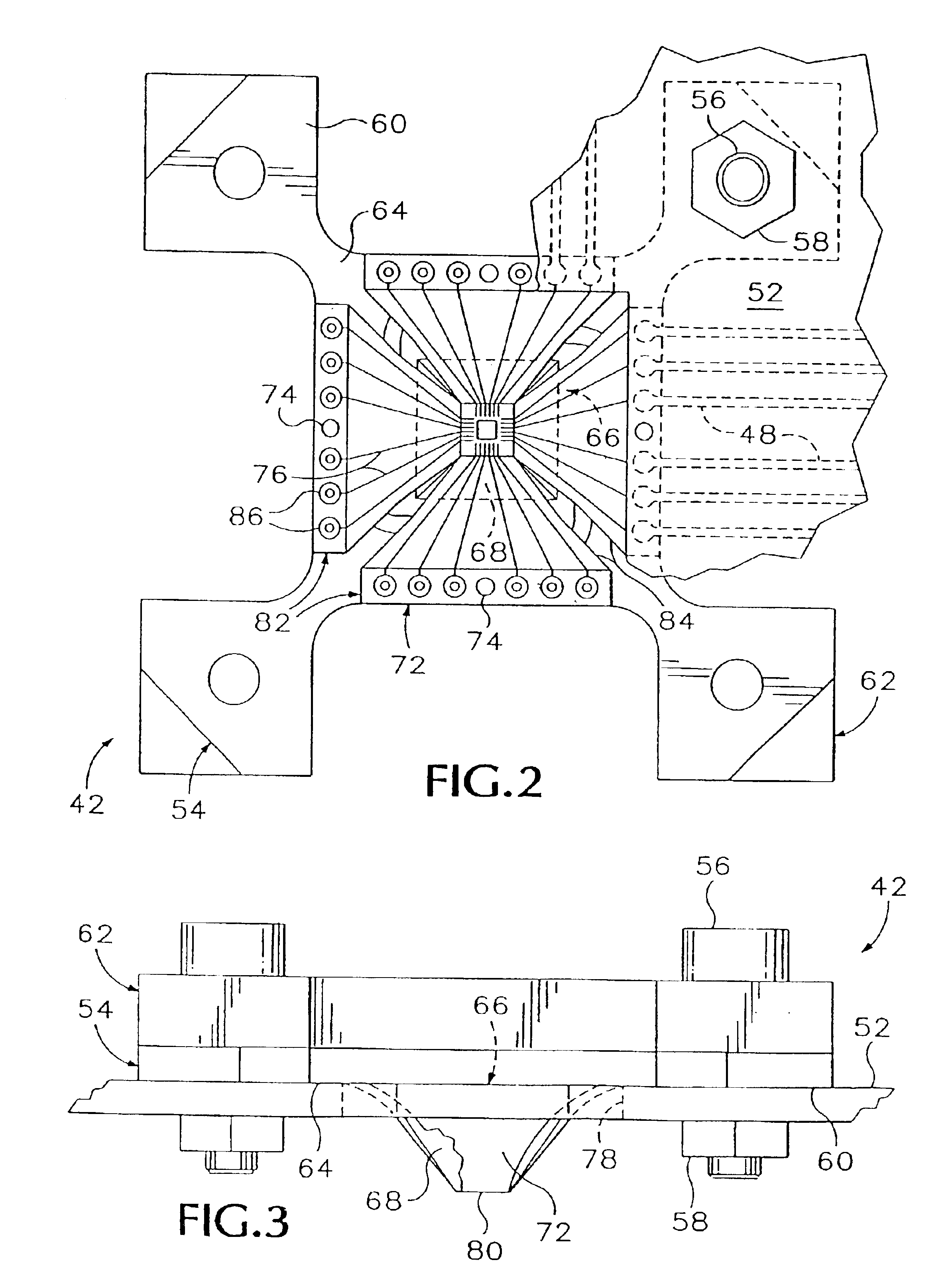
[0036]The probe head 40 includes a probe card 52 on which the data / signal lines 48 and 50 are arranged. Referring to FIGS. 2-3, the membrane probing assembly 42 includes a support element 54 formed of incompressible material such as a hard polymer. This element is detachably connected to the upper side of the prob...


PUM


Abstract

A membrane probing assembly includes a support element having an incompressible forward support tiltably coupled to a rearward base and a membrane assembly, formed of polyimide layers, with its central region interconnected to the support by an elastomeric layer. Flexible traces form data/signal lines to contacts on the central region. Each contact comprises a rigid beam and a bump located in off-centered location on the beam, which bump includes a contacting portion. After initial touchdown of these contacting portions, further over-travel of the pads causes each beam to independently tilt locally so that different portions of each beam move different distances relative to the support thus driving each contact into lateral scrubbing movement across the pad thereby clearing away oxide buildup. The elastomeric member backed by the incompressible support ensures sufficient scrub pressure and reliable tilt recovery of each contact without mechanical straining of the beam. In an alternative embodiment, the contacts comprise conductive beams each supported on a loose U-shaped flap formed in the membrane assembly where each flap and beam is tiltably supported in inclined position by an elastomeric hub interposed between the flap and support.

Description

CROSS REFERENCE TO RELATED APPLICATIONS[0001]This application is a continuation of U.S. application Ser. No. 09 / 174,384, filed Oct. 16, 1998, now U.S. Pat. No. 6,307,387 B1; which is a continuation of U.S. application Ser. No. 08 / 695,077, filed Aug. 8, 1996, now U.S. Pat. No. 5,914,613.BACKGROUND OF THE INVENTION[0002]The present invention relates to probe assemblies of the type commonly used for testing the individual devices that comprise an integrated circuit (IC) and, in particular, the present invention relates to a membrane probing assembly having contacts which scrub, in a locally controlled manner, across the respective input / output conductors of each device so as to reliably wipe clear the surface oxides that are normally found on those conductors thereby ensuring good electrical connection between the probing assembly and each device.[0003]The trend in electronic production has been toward increasingly smaller geometries particularly in integrated circuit technology wherei...

Claims


Application Information

Patent Timeline
IPC IPC(8): G01R1/073G01R1/067G01R1/06G01R31/26G01R31/02G01R31/28H01L21/66
CPCG01R1/06711G01R1/07342G01R1/0735
Inventor GLEASON, K. REEDSMITH, KENNETH R.BAYNE, MIKE
Owner CASCADE MICROTECH
Why Eureka
Try Eureka