
Transflective liquid crystal display device and fabricating method thereof

a liquid crystal display and reflector technology, applied in semiconductor devices, identification means, instruments, etc., can solve problems such as the inability to obtain uniform color purity, and achieve the effects of improving light efficiency, uniform color difference, and simple structur

Inactive Publication Date: 2005-08-09
LG DISPLAY CO LTD
View PDF7 Cites 44 Cited by
  • Summary
  • Abstract
  • Description
  • Claims
  • Application Information

AI Technical Summary

Benefits of technology

The present invention provides a liquid crystal display device with a reflective portion in the pixel region, which has improved light efficiency, uniform color difference, and production yield. The device includes a thin film transistor, a common line, a buffer layer, a reflective layer, a transparent electrode, and a color filter layer. The fabricating method of the device includes forming a gate line, a gate electrode, and a common line on a substrate, adding a first insulating layer, an active layer, and source and drain electrodes, adding a second insulating layer, adding a reflective layer, adding a third insulating layer, adding a transparent electrode, and adding a color filter layer. The technical effects of the invention include improved light efficiency, uniform color difference, and production yield.

Problems solved by technology

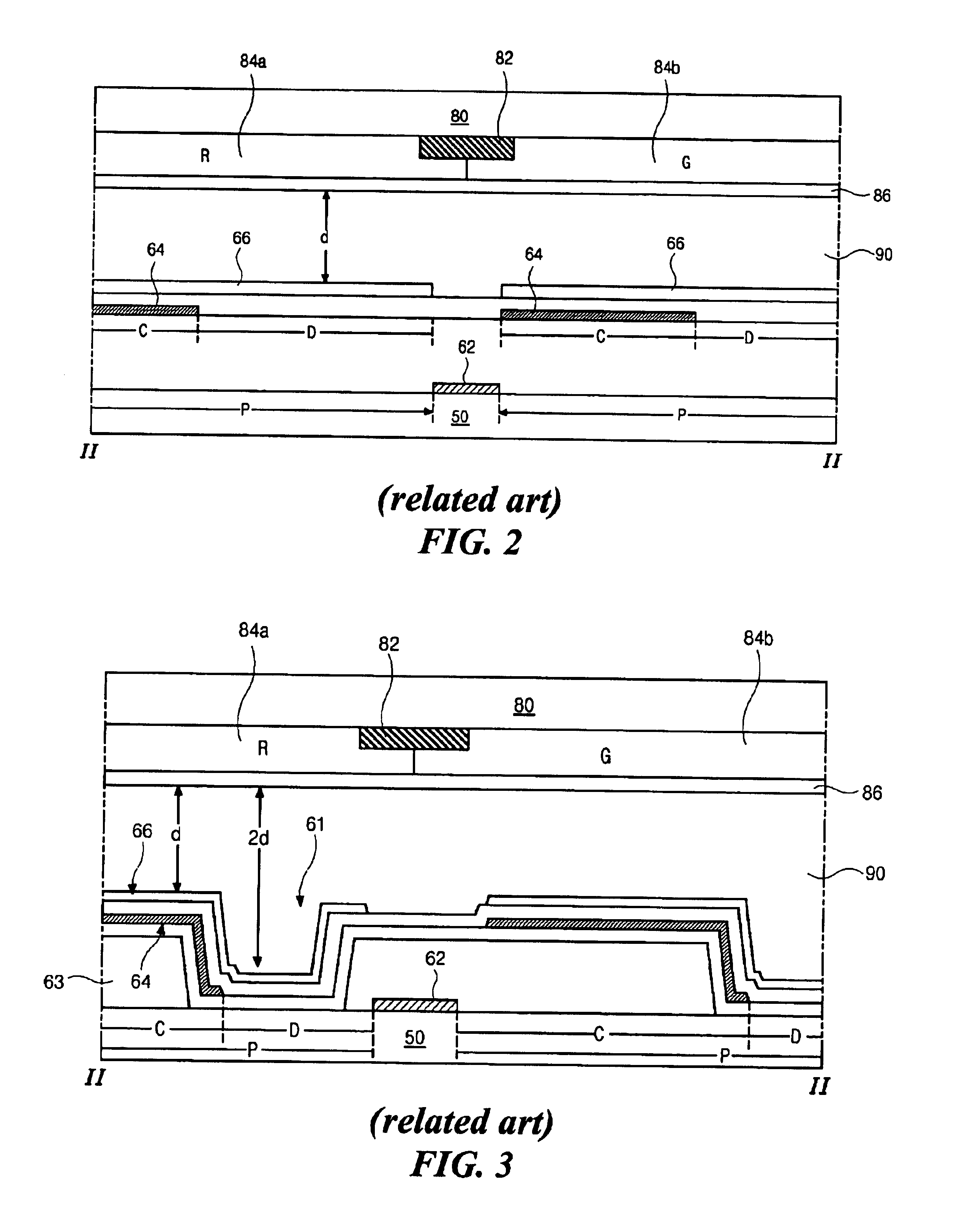
However, even though light efficiency of the reflective portion “C” is the same as that of the transmissive portion “D” due to the dual cell gap, uniform color purity cannot be obtained.

Method used


Image

  • Transflective liquid crystal display device and fabricating method thereof
  • Transflective liquid crystal display device and fabricating method thereof
  • Transflective liquid crystal display device and fabricating method thereof

Examples


Embodiment Construction

[0045]Reference will now be made in detail to embodiments of the present invention, examples of which are illustrated in the accompanying drawings. Wherever possible, similar reference numbers will be used throughout the drawings to refer to the same or like parts.

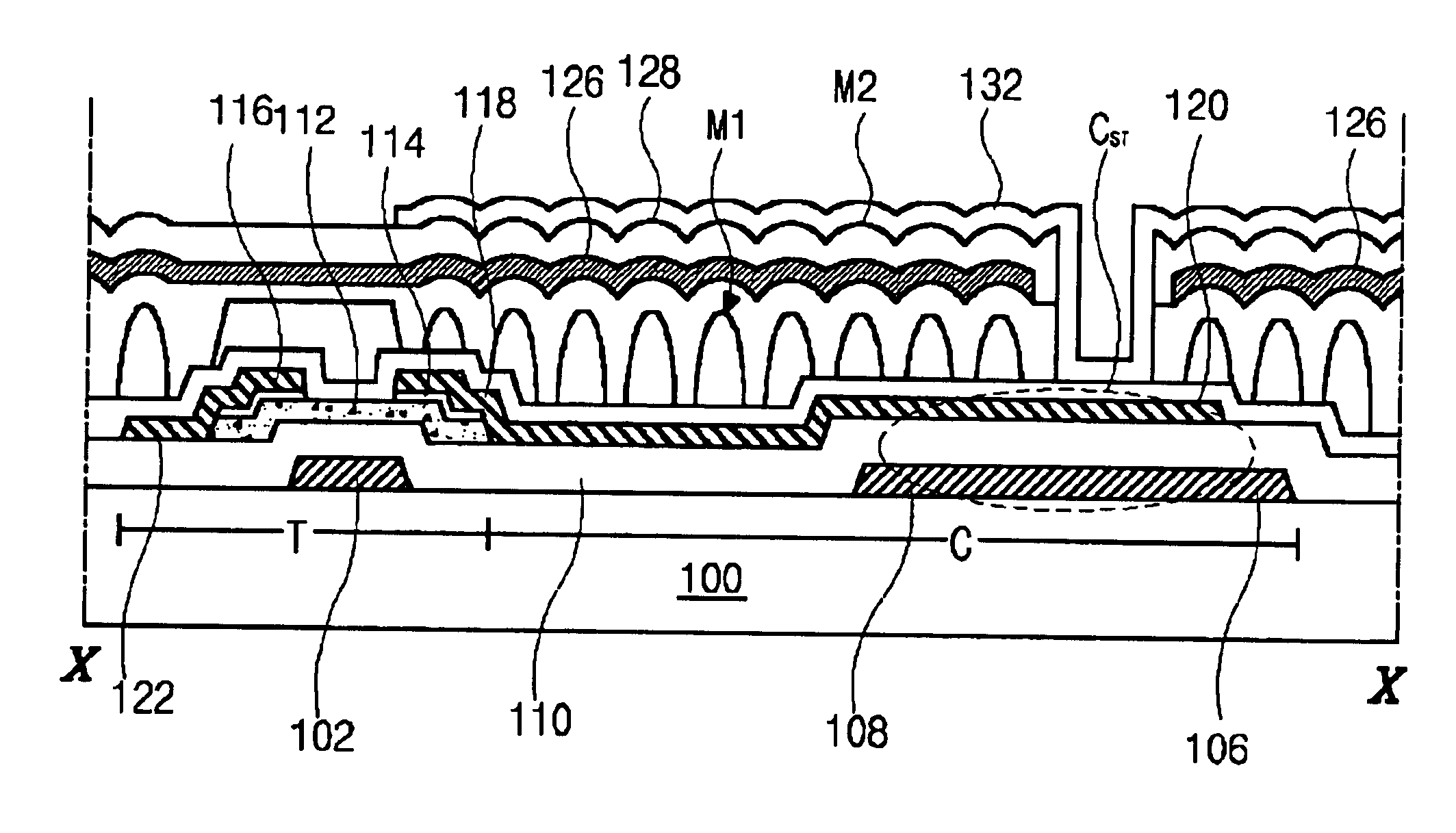
[0046]FIG. 7 is a schematic plane view of an array substrate for a transflective liquid crystal display device according to an embodiment of the present invention. A gate line 104 and a data line 122 are formed on a first substrate 100. The gate line 104 and the data line 122 cross each other to define a pixel region “P” including a reflective portion “C” and a transmissive portion “D.” A thin film transistor (TFT) “T” including a gate electrode 102, an active layer 112, and source and drain electrodes 116 and 118 is formed adjacent to a cross of the gate line 104 and the data line 122. The gate electrode 102 is connected to the gate line 104 and the source electrode 116 is connected to the data line 122. The active layer ...


PUM

PropertyMeasurementUnit
diameteraaaaaaaaaa
thicknessaaaaaaaaaa
thicknessaaaaaaaaaa

Abstract

An array substrate for a transflective liquid crystal display device includes: a gate line on a substrate; a data line crossing the gate line to define a pixel region having a transmissive portion and a reflective portion; a common line parallel to and spaced apart from the gate line; a thin film transistor connected to the gate and data lines, the thin film transistor including a gate electrode, an active layer, and source and drain electrodes; a capacitor electrode extending from the drain electrode and overlapping the common line; a reflective layer covering the common line and the thin film transistor and corresponding to the reflective portion; and a transparent electrode connected to the drain electrode and disposed in the pixel region.

Description

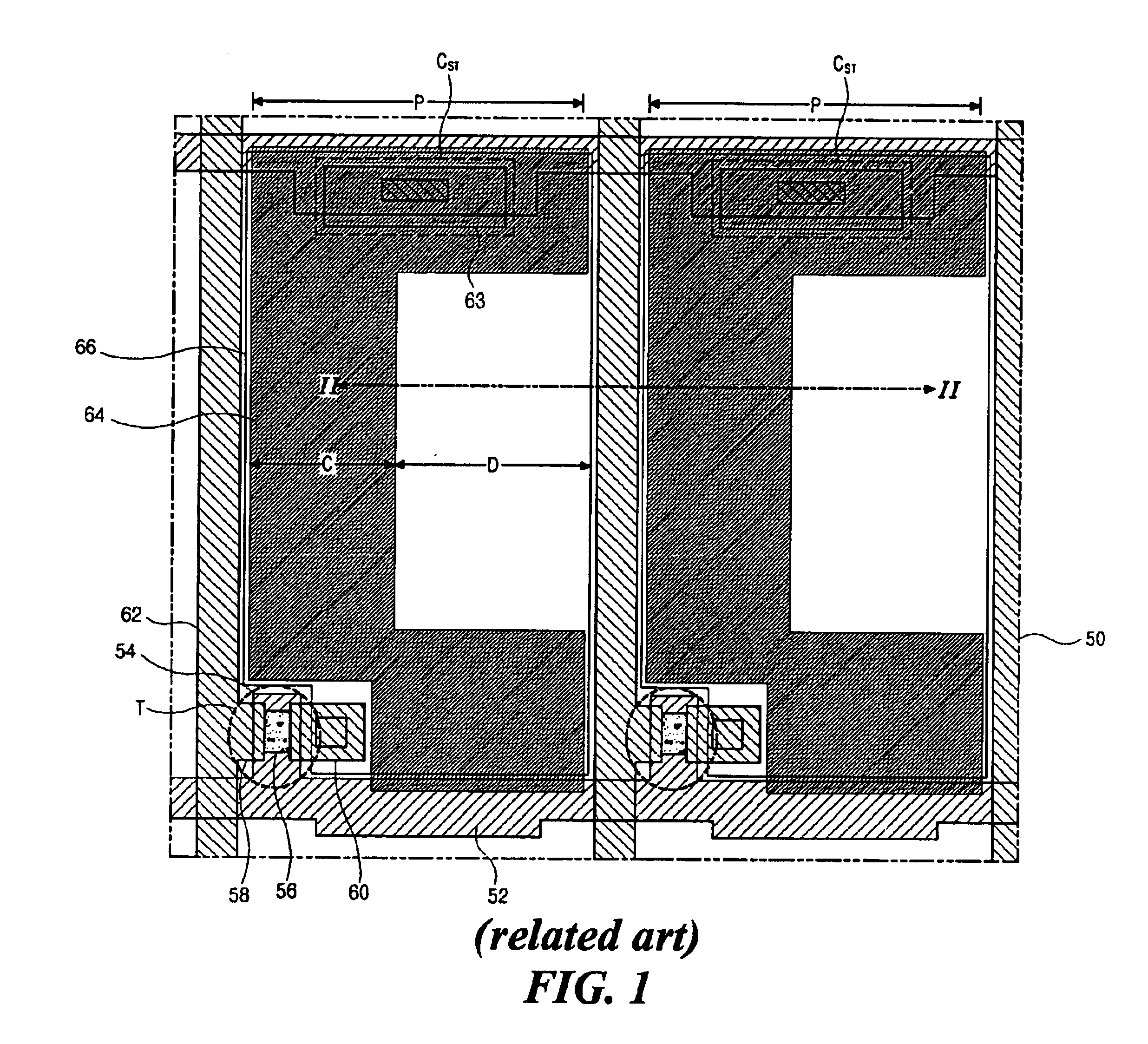
[0001]This application claims the benefit of Korean Patent Application No. 2002-88495, filed on Dec. 31, 2002, which is hereby incorporated by reference for all purposes as if fully set forth herein.BACKGROUND OF THE INVENTION[0002]1. Field of the Invention[0003]The present invention relates to a liquid crystal display device, and more particularly to a transflective liquid crystal display device selectively using reflective and transmissive modes, and a fabricating method thereof.[0004]2. Discussion of the Related Art[0005]Generally, transflective liquid crystal display (LCD) devices function as both transmissive and reflective LCD devices at the same time. Because the transflective LCD devices can use both the light from a backlight, and exterior natural or artificial light, transflective LCD devices may be used in more circumstances and the power consumption of the transflective LCD devices may be reduced.[0006]FIG. 1 is a schematic cross-sectional view of an array substrate for ...

Claims


Application Information

Patent Timeline
Patent Type & Authority Patents(United States)
IPC IPC(8): G02F1/13G02F1/1335H01L27/12G02F1/1333G02F1/1362G02F1/1368G09F9/30G09F9/35H01L21/77H01L21/84H01L27/13
CPCG02F1/133512H01L27/1255G02F1/133555G02F1/133371G02F1/136213G02F1/1335
Inventor JANG, SANG-MINCHOI, SU-SEOK
Owner LG DISPLAY CO LTD
Learn More