Matrix optical process correction

a technology of matrix optical process and layout verification, applied in the direction of microlithography exposure apparatus, instruments, photomechanical treatment, etc., can solve the problems of circuit elements to be created on a wafer, and affecting the appearance of objects on the wafer

Inactive Publication Date: 2005-08-09
SIEMENS PROD LIFECYCLE MANAGEMENT SOFTWARE INC
View PDF33 Cites 95 Cited by
  • Summary
  • Abstract
  • Description
  • Claims
  • Application Information

AI Technical Summary

Benefits of technology

[0010]The present invention is a method for performing optical process correction (OPC) or other verification techniques that analyze the interaction between a fragment in a mask layout and one or more edges to be created on a wafer. In one embodiment, a gradient matrix is calculated...

Problems solved by technology

As integrated circuits become more complex, the number of circuit elements to be created on a wafer become increasingly large and each object becomes correspondingly smaller.
As the size of the objects to be created become similar in size or smaller than the wavelength of light used to illuminate the wafer, distortions occur whereby the pattern of objects formed on the wafer do not correspond to the pattern of objects defined by the mask.
Each fragment can potentially affect the creation of many edges that lie within a predefined optical radius.
However, in pract...

Method used


Image

  • Matrix optical process correction
  • Matrix optical process correction
  • Matrix optical process correction

Examples


Embodiment Construction

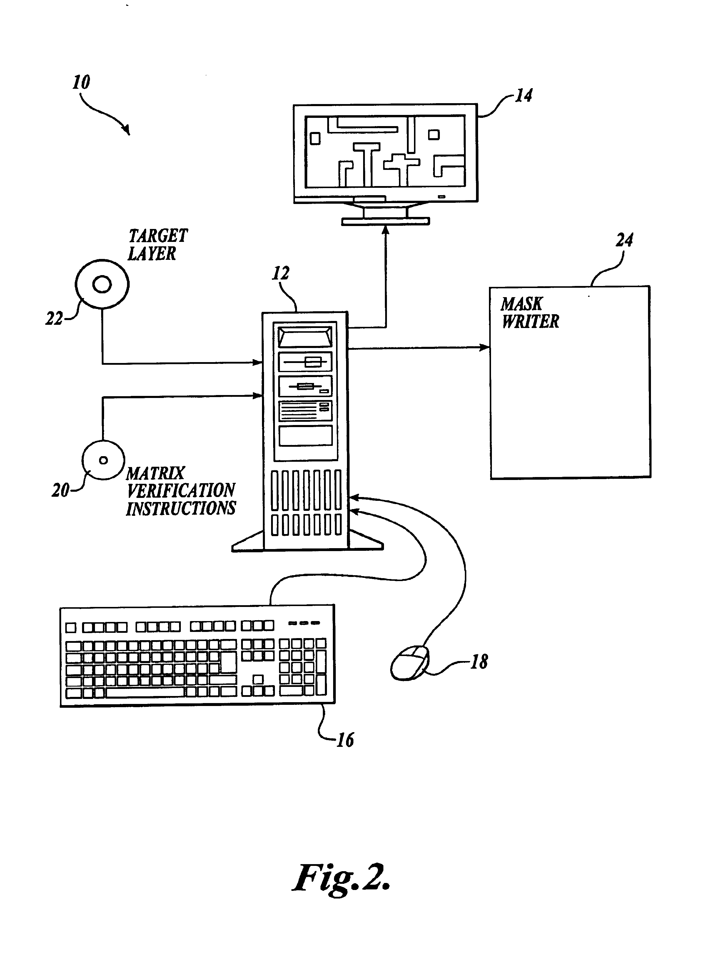
[0021]FIG. 2 illustrates one embodiment of a computer system that is used to perform a matrix-based verification technique such optical process correction (OPC) in accordance with the present invention. The computer system 10 includes a stand-alone or networked processor 12 having a visual display 14 and data input mechanism such as a keyboard 16 and mouse 18. Instructions used by the processor 12 to implement the matrix-based verification technique of the present invention are received on a computer readable media such as a CD-ROM or DVD 20 or can be received as a communication signal from a remote computer over a wired or wireless data link. As will be described in further detail below, the processor 12 receives a target layer description that defines a number of circuit elements to be created on a semiconductor wafer. The target layer description is received on a computer readable media 22 or can be received from a remote computer over a wired or wireless data communication link....


PUM


Abstract

A method for performing a matrix-based verification technique such as optical process correction (OPC) that analyzes interactions between movement of a fragment on a mask and one or more edges to be created on a wafer. In one embodiment, each edge to be created is analyzed and one or more fragments of a mask are moved in accordance with a gradient matrix that defines how changes in position of a fragment affect one or more edges on the mask. Fragments are moved having a significant effect on an edge in question. Simulations are performed and fragments are moved in an iterative fashion until each edge has a objective within a prescribed tolerance. In another embodiment, each edge has two or more objectives to be optimized. A objective is selected in accordance with a cost function and fragments are moved in a mask layout until each edge has acceptable specification for each objective.

Description

CROSS-REFERENCE TO RELATED APPLICATION[0001]The present application claims the benefit under 35 U.S.C. § 119(e) of the U.S. Provisional Application No. 60 / 437,874, filed Jan. 2, 2003, titled USING OPC TO OPTIMIZE FOR IMAGE SLOPE AND IMPROVE PROCESS WINDOW, which is herein incorporated by reference.FIELD OF THE INVENTION[0002]The present invention relates to semiconductor layout verification techniques, and in particular to methods of enhancing the manufacturability of circuit designs that are created by photolithography.BACKGROUND OF THE INVENTION[0003]The most common technique for forming circuit elements on a semiconductor wafer is by photolithographic printing whereby one or more reticles (also more commonly called masks or photomasks) are used to form a pattern and selectively expose areas of photosensitive resist layers on the wafer. As integrated circuits become more complex, the number of circuit elements to be created on a wafer become increasingly large and each object beco...

Claims


Application Information

Patent Timeline
IPC IPC(8): G06F17/50G03F7/20
CPCG03F7/70433G03F7/705
Inventor GRANIK, YURICOBB, NICOLAS
Owner SIEMENS PROD LIFECYCLE MANAGEMENT SOFTWARE INC
Why Eureka
Try Eureka