
Direct injection engine

a direct injection and engine technology, applied in the direction of combustion engines, cylinders, machines/engines, etc., can solve the problems of deteriorating combustion stability, weakening squish flow, and reducing the integrity of tumble flow, so as to improve fuel economy and engine power, increase combustion stability, and improve combustion characteristics.

Inactive Publication Date: 2005-08-16
HYUNDAI MOTOR CO LTD
View PDF3 Cites 21 Cited by
  • Summary
  • Abstract
  • Description
  • Claims
  • Application Information

AI Technical Summary

Benefits of technology

The present invention provides a direct injection engine with improved combustion stability, fuel economy, and engine power. The engine has a combustion chamber with a pent roof shape and a piston head with a curved surface. The engine also has an intake valve, exhaust valve, and fuel injector for directly injecting fuel into the combustion chamber. The engine has a bowl with a curved surface that is connected to the intake valve and has a predetermined curvature. The intake valve pocket is formed as a single groove to receive all intake valves. The engine also has a split wall in the intake port and a valve to selectively open or close the lower passageway. These features improve combustion characteristics, minimize wall wetting, and reduce hydrocarbon emissions.

Problems solved by technology

Such separation phenomenon may deteriorate the combustion stability and the injected fuel may contact oil so that a carbon layer can be formed.
This may decrease an integrity of the tumble flow and also weaken a squish flow, and this may be a cause of incomplete combustion.
The step portion may hinder a spread of firing and this may cause a knocking.

Method used


Image

  • Direct injection engine
  • Direct injection engine
  • Direct injection engine

Examples


Embodiment Construction

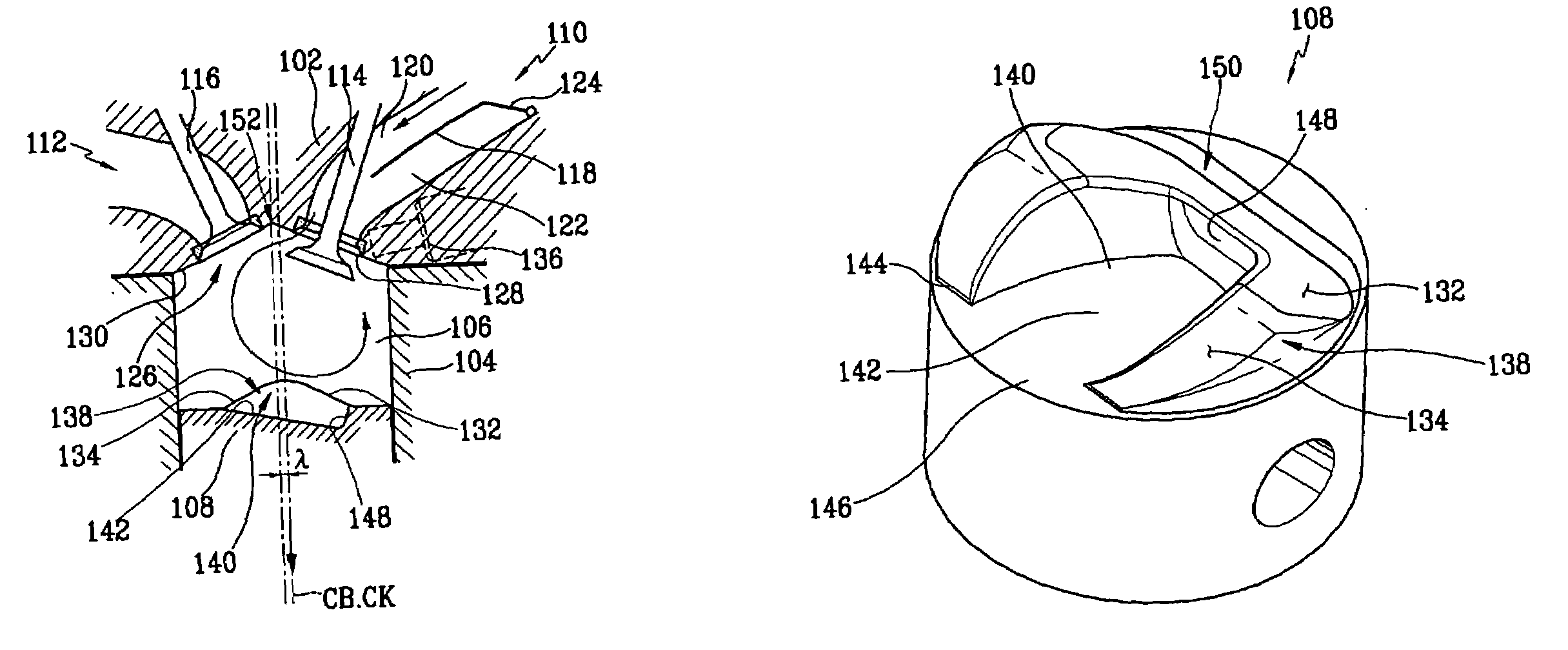
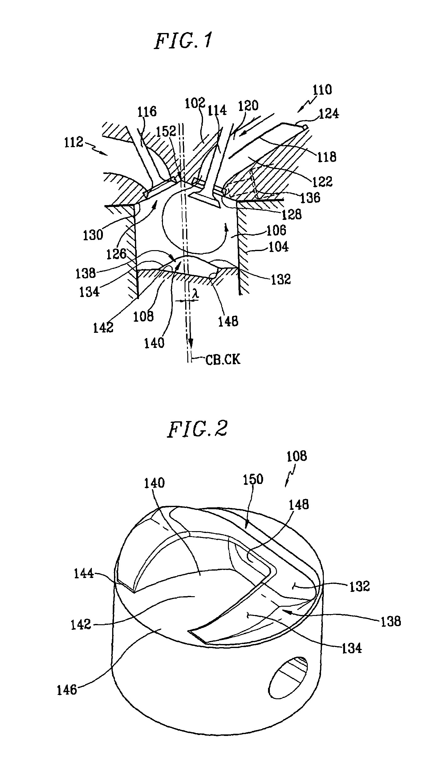
[0026]According to FIG. 1, a main body of an engine is formed by a combination of a cylinder head 102 and a cylinder block 104. A piston 108 is vertically slidably disposed in a cylinder 106 that is defined within the cylinder block 104. An intake port 110 and an exhaust port 112 are formed in the cylinder head 102. The number of the intake port 110 and the exhaust port 112 depend on the number of intake and exhaust valves 114 and 116 employed in the engine.

[0027]A split wall 118 is disposed in a downstream direction of the intake port 110, which divides the intake port 110 into an upper passageway 120 and a lower passageway 122. A valve 124 is disposed in an inlet portion of the lower passageway 122 and selectively opens and closes the lower passageway 122. The valve 124 is operated by a drive motor that is controlled by an engine control unit. According to engine operating conditions, the valve 124 is controlled to be opened or closed by the engine control unit. When an air-fuel m...


PUM


Abstract

An exhaust-valve-side portion of a bottom surface of a bowl is connected to an upper surface of a piston by a smoothly curved surface. Therefore, a separation of a tumble flow can be minimized and air flow introduced into the bowl is more strongly tumbled. Fuel mixed with the air flow is also introduced into the bowl, so a generation of a carbon layer that is caused by contact of fuel and oil with the wall can be prevented. A width of the exhaust-valve-side portion of the bowl is greater than a width of the intake-valve-side portion of the bowl and the side walls of the bowl are formed as curved surfaces. The intake valve pocket is formed as a single groove, accumulation of carbon can be minimized, and propagation of a flame during the combustion occurs easily.

Description

CROSS REFERENCE TO RELATED APPLICATIONS[0001]This application claims priority of Korean Application No. 10-2003-0100886, filed on Dec. 30, 2003, the disclosure of which is incorporated herein by reference.TECHNICAL FIELD OF THE INVENTION[0002]The present invention generally relates to a direct injection engine. More particularly, the direct injection engine tumbles the intake air flow in order to increase fuel economy and decrease an amount of noxious exhaust gas generated during cold start.BACKGROUND OF THE INVENTION[0003]A gasoline direct injection engine is an engine that has advantages of both a gasoline engine and a diesel engine. These advantages generate a high fuel economy engine. In the gasoline direct injection engine, fuel is directly injected into a combustion chamber. In this gasoline direct injection engine, intake flow is a very important factor in determining engine efficiency. The intake flow is determined by the shape of the intake ports, the combustion chamber, an...

Claims


Application Information

Patent Timeline
Patent Type & Authority Patents(United States)
IPC IPC(8): F02B23/10F02B31/00F02B31/04F02B31/08F02F1/24F02B23/00F02F1/42F02F3/26F02F3/28F02B3/06F02B75/12
CPCF02B23/104F02B31/085F02B2023/106F02B2075/125F02B2275/48F02F2001/241Y02T10/125Y02T10/146Y02T10/123Y02T10/12F02F3/28
Inventor YU, CHUL HO
Owner HYUNDAI MOTOR CO LTD
Learn More