Sterile filling machine having needle filling station within e-beam chamber

a technology of e-beam chamber and filling machine, which is applied in the directions of bundling machine details, liquid handling, packaging goods types, etc., can solve the problems of contaminating containers, wasting time, and more defective dispensers than otherwise desired, so as to eliminate any risk of contamination

Inactive Publication Date: 2005-08-16
MEDINSTILL DEV
View PDF42 Cites 71 Cited by
  • Summary
  • Abstract
  • Description
  • Claims
  • Application Information

AI Technical Summary

Benefits of technology

[0011]In one embodiment of the present invention, the apparatus comprises a laser source for transmitting laser radiation at a predetermined wavelength and power, and a container including a heat resealable stopper and a chamber for receiving the substance therein. The resealable stopper includes a thermoplastic body defining (i) a predetermined wall thickness in an axial direction thereof, (ii) a predetermined color and opacity that substantially absorbs the laser radiation at the predetermined wavelength and substantially prevents the passage of the radiation through the predetermined wall thickness thereof, and (iii) a predetermined color and opacity that causes the laser radiation at the predetermined wavelength and power to hermetically seal a needle aperture formed in the needle penetration region thereof in a predetermined time period.
[0022]One advantage of the apparatus and method of the present invention is that it substantially eliminates any risk of contaminating the containers between sterilization and filling because the needle or like filling member is located within the e-beam chamber.

Problems solved by technology

One of the drawbacks of such prior art dispensers, and processes and equipment for filling such dispensers, is that the filling process is time consuming, and the processes and equipment are expensive.
Further, the relatively complex nature of the filling processes and equipment can lead to more defectively filled dispensers than otherwise desired.

Method used


Image

  • Sterile filling machine having needle filling station within e-beam chamber
  • Sterile filling machine having needle filling station within e-beam chamber

Examples


Embodiment Construction

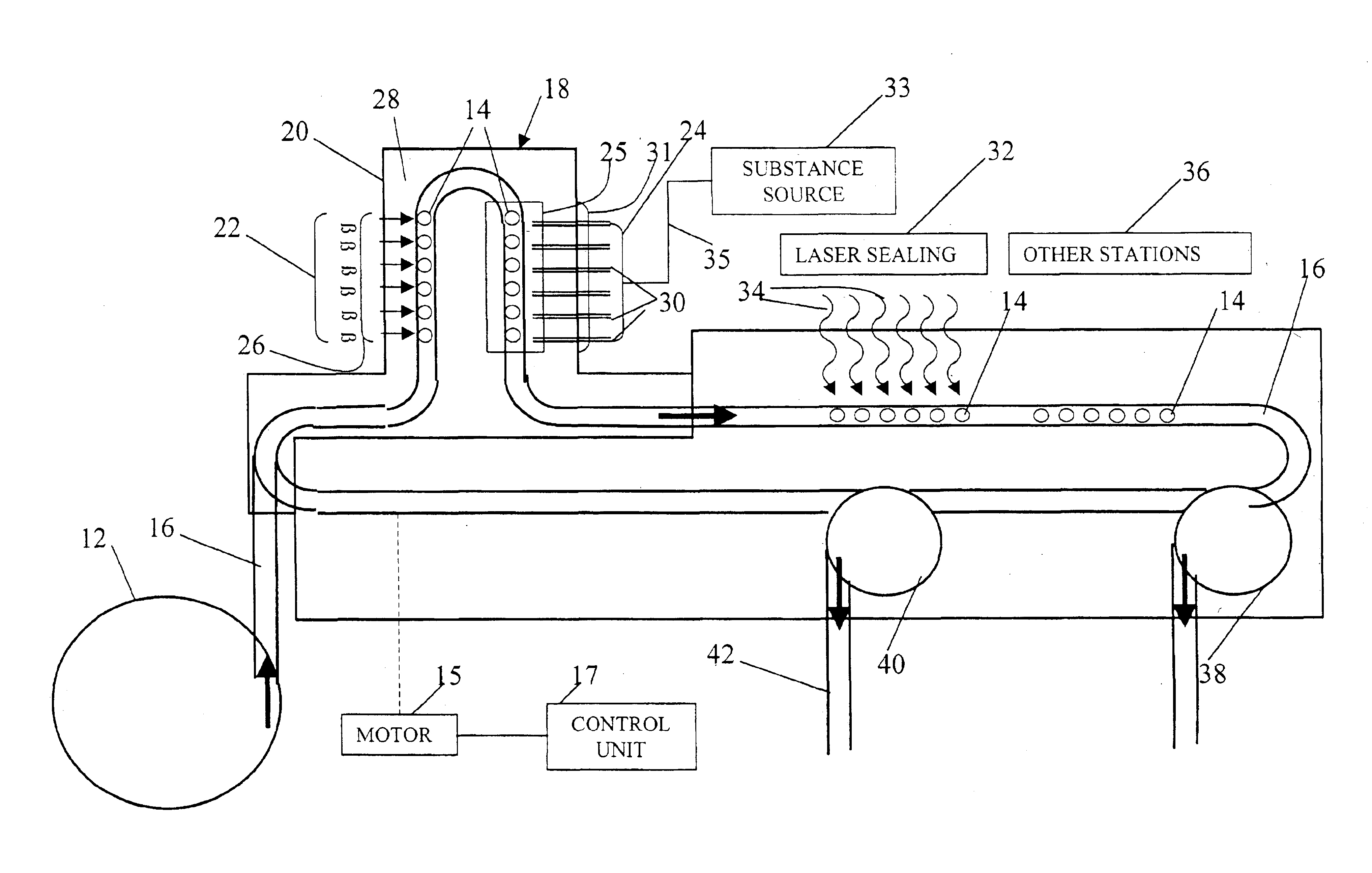
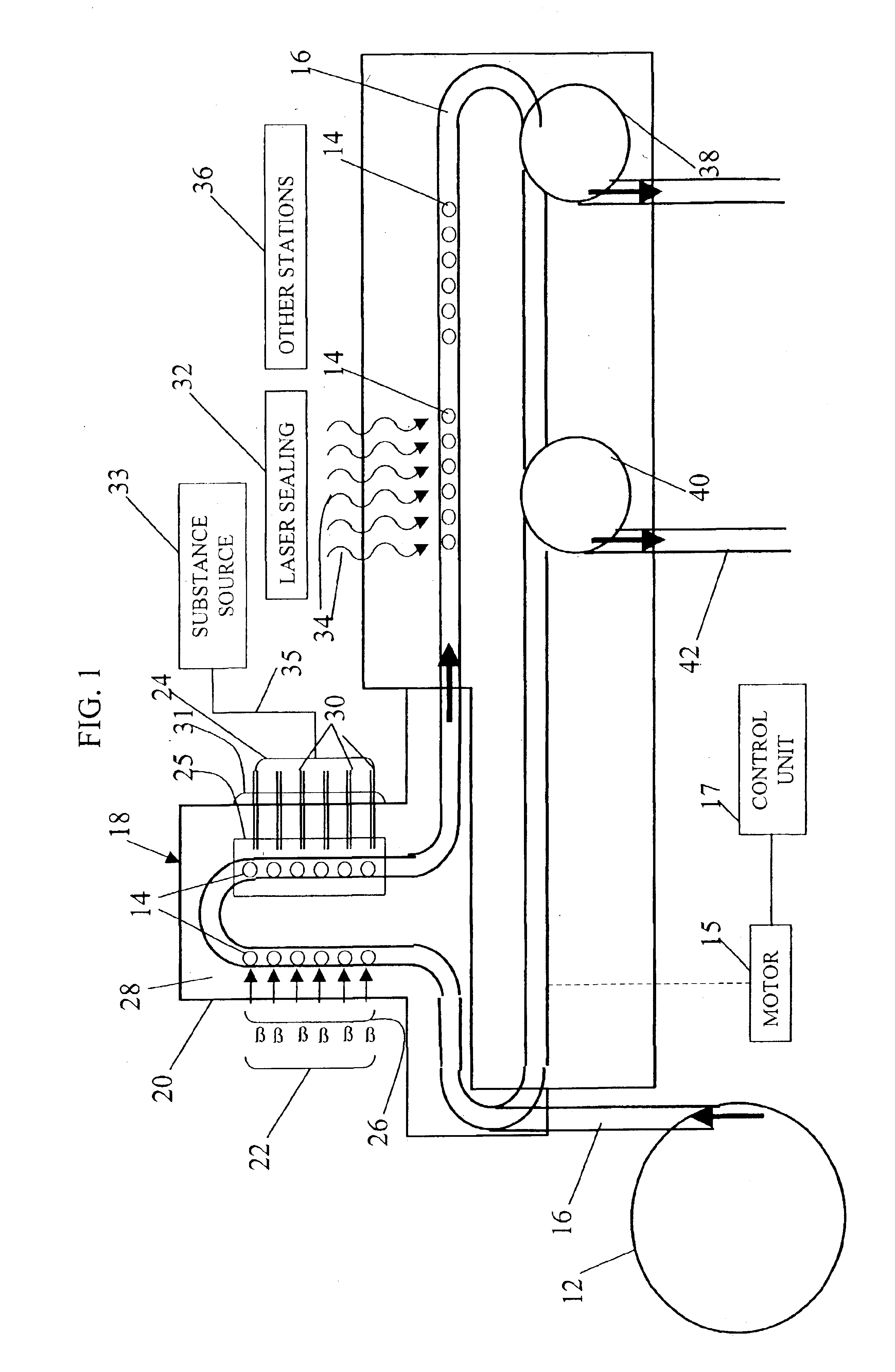
[0025]In FIG. 1, a sterile filling machine (“SFM”) embodying the present invention is indicated generally by the reference numeral 10. In the currently preferred embodiment of the invention, the SFM 10 is used to fill vials or syringes for containing medicaments, such as vaccines or pharmaceutical products. However, as may be recognized by those of ordinary skill in the pertinent art based on the teachings herein, the SFM 10 equally may be used for filling any of numerous other types of containers or delivery devices with the same or other substances, such as cosmetics and food products. The SFM 10 comprises an infeed unit 12 for holding the vials, syringes or other containers 14 to be delivered into the SFM. In the illustrated embodiment of the present invention, the infeed unit 12 is in the form of a rotary table that holds a plurality of vials, syringes or other containers 14, and delivers the containers at a predetermined rate into the SFM. As may be recognized by those of ordin...


PUM

PropertyMeasurementUnit
time periodaaaaaaaaaa
timeaaaaaaaaaa
timeaaaaaaaaaa

Abstract

A sterile filling machine and related method are provided for sterile filling a container with a substance. The container includes a heat resealable stopper and a chamber for receiving the substance therein. The sealed, empty containers are subjected to radiation capable of penetrating through the stopper and chamber for sterilizing the container. The previously sterilized containers are then transported through an e-beam chamber, wherein an electron beam is directed onto a penetrable surface of the stopper to sterilize the penetrable surface. A needle is mounted within the e-beam chamber and moved into engagement with the stopper to pierce the sterilized penetrable surface of the stopper and inject the substance through the needle and into the chamber of the container. The needle is then withdrawn from the stopper and the filled container is transported outside of the e-beam chamber. Laser energy is then transmitted onto the penetrated surface of the stopper to fuse the stopper material and hermetically re-seal the stopper.

Description

CROSS-REFERENCE TO RELATED APPLICATION[0001]This patent application claims priority on U.S. Provisional Application Ser. No. 60 / 390,212, filed Jun. 19, 2002, entitled “Sterile Filling Machine Having Needle Filling Station Within E-Beam Chamber”, which is hereby expressly incorporated by reference as part of the present disclosure.FIELD OF THE INVENTION[0002]The present invention relates to apparatus and methods for filling medicaments or other substances into containers, and more particularly, to apparatus and methods for sterile filling medicaments or other substances into hermetically sealed containers, such as vials or syringes.BACKGROUND INFORMATION[0003]A typical medicament dispenser includes a body defining a storage chamber, a fill opening in fluid communication with the body, and a stopper or cap for sealing the fill opening after filling the storage chamber to hermetically seal the medicament within the dispenser. In order to fill such prior art dispensers with a sterile fl...

Claims


Application Information

Patent Timeline
Patent Type & Authority Patents(United States)
IPC IPC(8): B65B3/04B65B1/04B65B55/02B67C3/00B65B55/08A61BA61L2/08B65B7/28B65B55/04
CPCA61L2/08A61L2/087B65B3/003B65B7/16B65B7/161B65B55/025B65B55/08B65B55/16B65B3/04A61L2/24A61L2202/14
Inventor PY, DANIEL
Owner MEDINSTILL DEV
Why Eureka
Try Eureka