Engine arrangement for a four cycle engine

a four-cycle engine and engine technology, applied in the direction of machines/engines, jet propulsion mounting, transportation and packaging, etc., can solve the problems of high production cost, inability to meet the needs of snowmobiles, and high production cost, so as to improve the manner in which snowmobiles handle, improve the charging effect, and reduce the inertia of snowmobiles

Inactive Publication Date: 2005-08-16
BRP ROTAX
View PDF13 Cites 20 Cited by
  • Summary
  • Abstract
  • Description
  • Claims
  • Application Information

AI Technical Summary

Benefits of technology

[0014]It is another object of the present invention to provide a four cycle engine having a low center of gravity for improved vehicle handling and maneuvering.
[0018]It is another object of the present invention to provide a four cycle engine having a small installed size and low weight with a high level of performance relative to the volumetric displacement of the engine.
[0022]It is another object of the present invention to arrange the induction system and the exhaust system on opposite sides of the engine, such that the combustion air is not heated to improve cylinder charging.
[0023]It is another object of the present invention to provide an engine that enhances the manner in which a snowmobile handles, whereby the resulting center of gravity that is determined by the vehicle frame and the engine is located as close as possible to the center of the vehicle in order to reduce the inertia of the snowmobile about its vertical axis.
[0026]To overcome the deficiencies of the prior art and achieve the above-described objectives, applicants have developed a four cycle engine for use in a vehicle, which produces a vehicle with a relatively low center of gravity for improved handling and maneuverability. The four cycle engine in accordance with the present invention has a crankcase having a crankshaft. The crankshaft has a crankshaft axis that is arranged transverse to the longitudinal axis of the vehicle.
[0030]The engine also includes at least one auxiliary unit connected to the crankcase. The auxiliary units include, but are not limited to a generator, an alternator, a water pump, an oil pump, and a charger. The auxiliary units are driven by a drive gearing having a toothed wheel gearing. Each of the auxiliary units are located on a side of the longitudinal axis of the vehicle opposite to the CVT. The toothed-wheel gearing may be located within a secondary housing connected to the crankcase. To improve handling and maneuverability of the vehicle, it is desirable to locate the centers of gravity of the auxiliary units to the rear side of the engine behind the crankshaft axis.

Problems solved by technology

Two-cycle engines, however, emit a considerable quantity of unburned hydrocarbons and other pollutants into the environment in the form of exhaust gas.
Considerable structural and design modifications must be incorporated into the two-cycle engine to comply with current and ever more rigorous emission control regulations, which results in higher production costs.
Furthermore, costly design features must be incorporated when the engines are used in snowmobiles to ensure that noise emissions are comparable to those of four-cycle engines.
As such, these vehicles are only suitable for small-scale production.
This arrangement is problematic especially for V-twin designs.
If the center of gravity of the engine and the center of gravity of the CVT are on the same side of the vehicle, this would have a negative impact on the balance of the snowmobile and handling is made more difficult.
This arrangement, however, would generate undesirable oscillations within the drive train, which could result in a reduction of the service life or the destruction of the drive train.
This arrangement is not possible in the Redline design because the engine would collide with the steering rod.
This snowmobile suffers from many of the same problems discussed above.
This engine has numerous drawbacks including a greater installed length and a greater weight.
This produces a significant buildup of heat beneath the tank and the seat.
This adversely impacts the handling and maneuverability of the snowmobile.
Second, the snowmobile is typically operated in severe working conditions (temperature changes between +15° C. to −40° C., ice formation, etc.).
The belt is prone to failure.

Method used


Image

  • Engine arrangement for a four cycle engine
  • Engine arrangement for a four cycle engine
  • Engine arrangement for a four cycle engine

Examples


Embodiment Construction

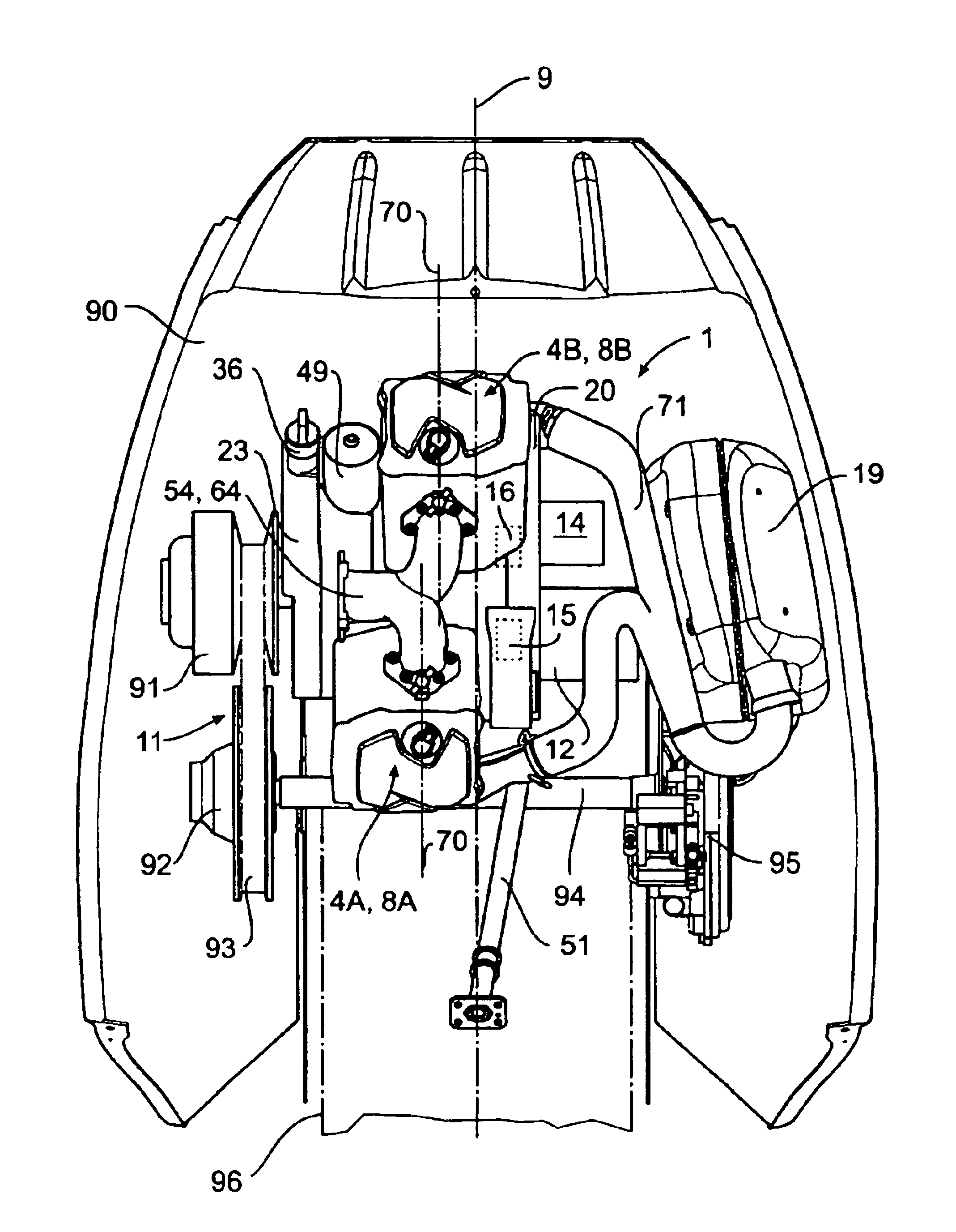
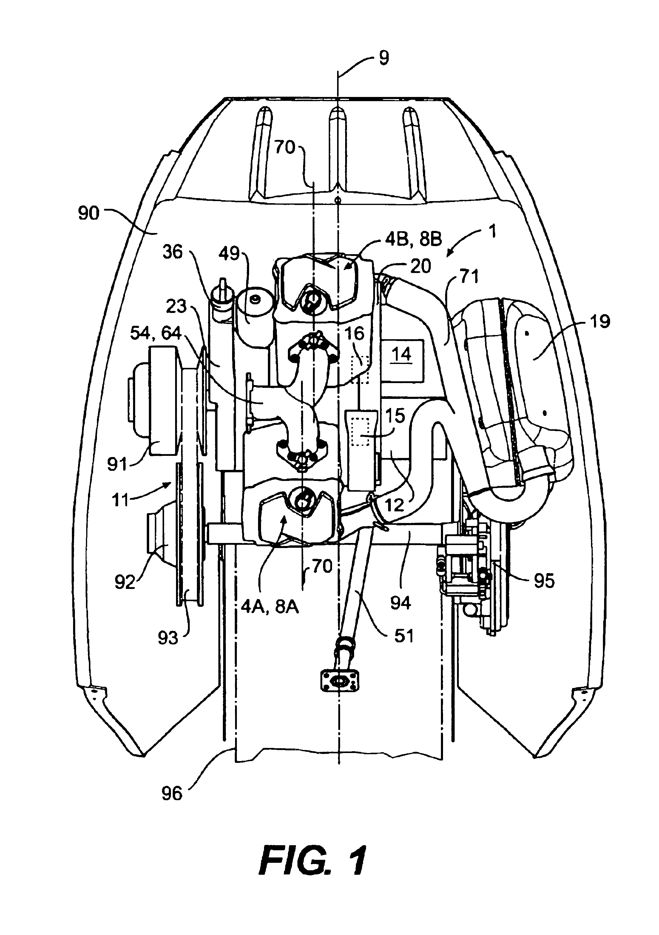
[0059]A four-cycle engine having one or more cylinders 4 will now be described in greater detail. A two cylinder engine 1 in accordance with the present invention is illustrated in FIG. 1. A single cylinder engine 100 in accordance with the present invention is illustrated in FIG. 9. As shown in FIG. 1, the engine 1 is mounted to a chassis of a snowmobile 90. The engine 100 may be similarly mounted in the chassis of the snowmobile 90. The present invention is not limited to four-cycle engines used in snowmobiles; rather, it is intended that the engines 1 and 100 disclosed herein and any variations thereof may be used in multiple vehicles including but not limited to three-wheeled vehicles, ATVs, motorcycles, and watercraft.

[0060]The four-cycle engine 1 having a pair of cylinders 4A and 4B will now be described in greater detail. Although a pair of cylinders 4A and 4B are disclosed, the present invention is not limited to a pair of cylinders; rather, it is contemplated that a single ...


PUM


Abstract

An arrangement of a four cycle engine is disclosed for use in a vehicle providing a relatively low center of gravity for improved handling and maneuverability. The engine components are located on opposing sides of the longitudinal axis of the vehicle and behind the axis of the crankshaft to move the center of gravity to the middle of the vehicle.

Description

CROSS REFERENCE TO RELATED APPLICATIONS[0001]This application is related to and claims priority to U.S. Provisional Patent Application Ser. No. 60 / 402,709, which was filed on Aug. 13, 2002.BACKGROUND OF THE INVENTION[0002]1. Field of the Invention[0003]The present invention relates to an engine arrangement for a four-cycle engine that is intended for use in a vehicle, such as for example a snowmobile or a three-wheeled vehicle. More particularly, the present invention relates to a four-cycle engine that complies with the strict emission control regulations currently developed in the United States without having a negative effect on the balance of the vehicle. The engines disclosed herein are described in connection with a snowmobile. The present invention, however, is not intended to be so limited; rather, it is contemplated that the engines described herein may be used in motorcycles, all-terrain vehicles, and various watercraft.[0004]2. Description of Related Art[0005]Snowmobiles ...

Claims


Application Information

Patent Timeline
Patent Type & Authority Patents(United States)
IPC IPC(8): B60K5/04B60K5/00F01M1/12F01M1/00F02B75/22F02B75/00F02B61/02F02B61/00F02B75/18F02B75/02
CPCB60K5/04F01M1/12F02B61/02F02B75/22B62M2027/023F01M2001/126F02B2075/027F02B2075/1808Y02T10/12
Inventor PICHLER, ANTONKUSEL, RUDOLFOHRNBERGER, GERDMATTE, SYLVAIN
Owner BRP ROTAX
Why Eureka
Try Eureka