Apparatus for intubation

Inactive Publication Date: 2005-08-16
HILL STEPHEN D
View PDF25 Cites 163 Cited by
  • Summary
  • Abstract
  • Description
  • Claims
  • Application Information

AI Technical Summary

Benefits of technology

[0009]In an alternative embodiment, the invention provides a vision system for obtaining an image of an inner cavity. The vision system includes a stylet having a first end, a second end and a flexible shaft disposed therebetween. The first end is placed within the cavity during use and the shaft has a lumen. The vision system further includes an optical system that is disposed within the lumen for providing light to illuminate a region proximal to the first end of the stylet and for obtaining an image of the illuminated region for displaying on a monitor. The vision system further includes an extension piece that is releasably connectable to the second end of the stylet to increase the length of the stylet.
[0010]In yet another alternative embodiment, the invention prov

Problems solved by technology

This difficult airway presents a challenge to the medical practitioner who is performing the intubation.
The difficult airway is particularly troublesome in the case of blind intubation, in which the vocal cords are not directly visible with a conventional laryngoscope.
As a result it is likely that the intubation process will fail.
Since 1992, failed intubations have resulted in one third of all anesthesia related deaths during operation procedures.
In addition, failed intubation may also lead to bleeding, swelling, la

Method used


Image

  • Apparatus for intubation
  • Apparatus for intubation
  • Apparatus for intubation

Examples


Embodiment Construction

[0025]The subject invention comprises a video scope, otherwise known as a “seeing eye stylet”, that is used in conjunction with an endotracheal tube during intubation. A conventional endotracheal tube will first be described. Several embodiments of the video scope will then be described followed by a description of several methods of use for the video scope.

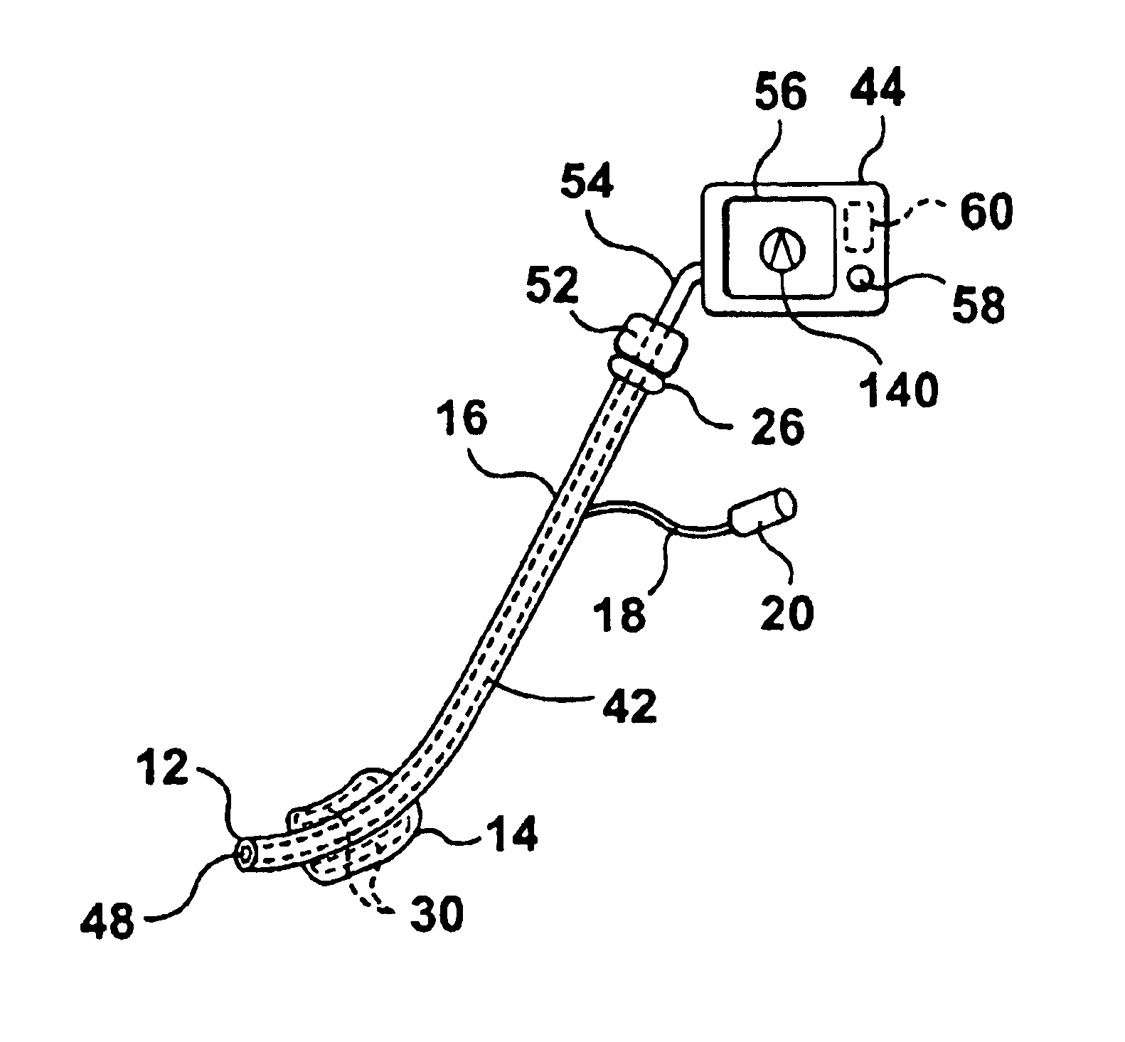
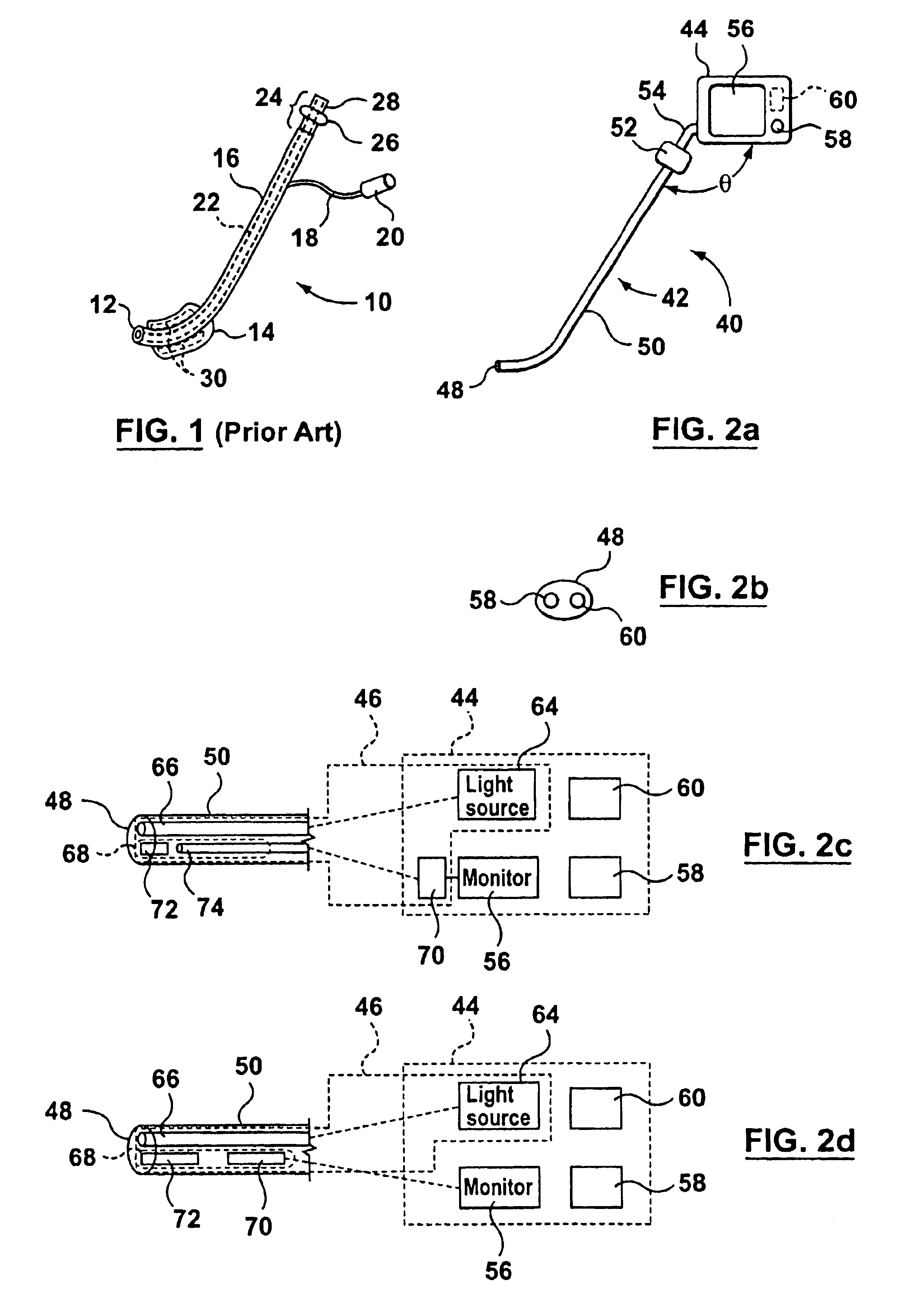
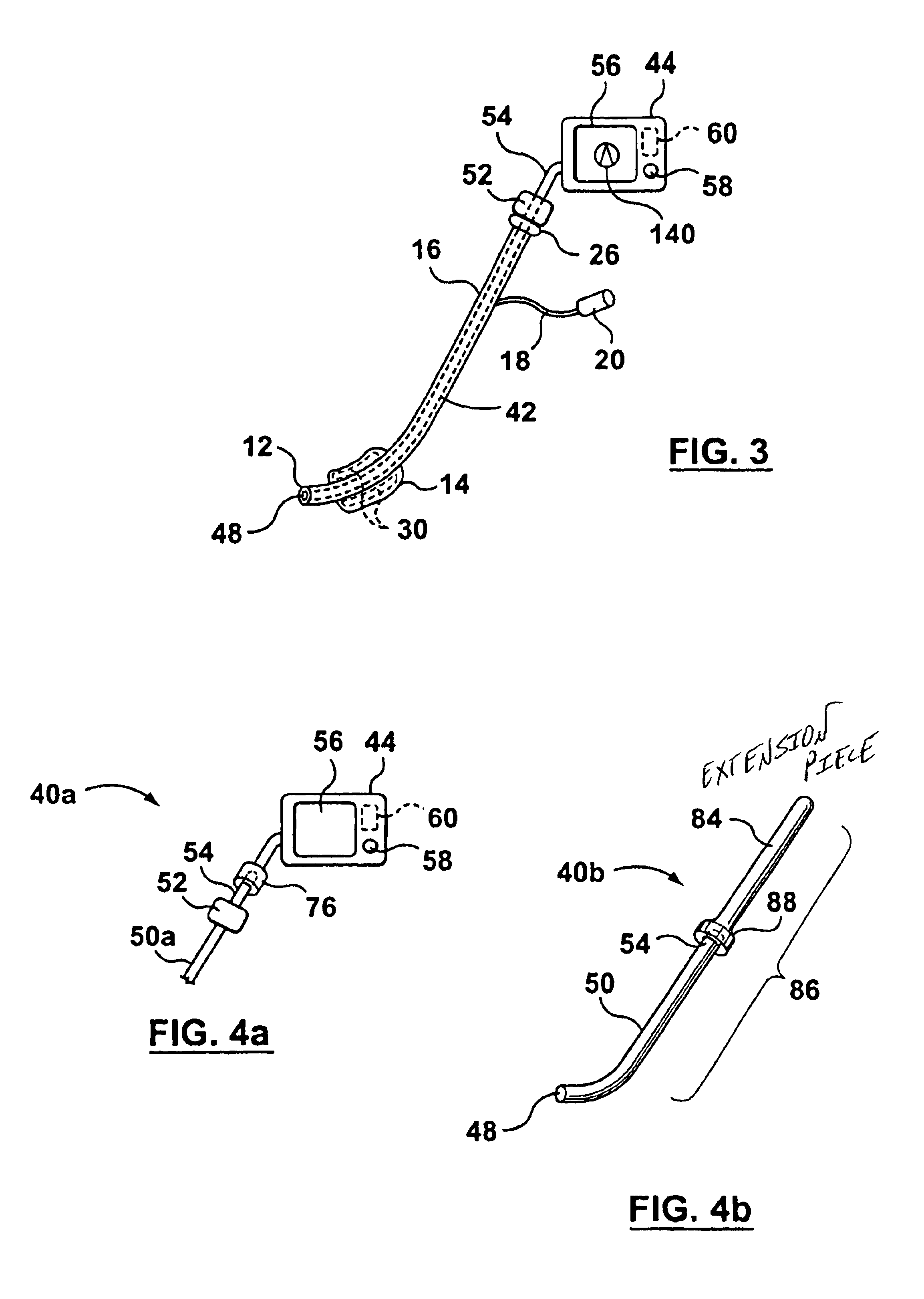
[0026]Referring to FIG. 1, shown therein is an endotracheal tube 10 which is used to intubate a patient. The endotracheal tube 10 comprises a first end (i.e. a tip) 12, a cuff 14, a shaft 16, a tube 18, a nozzle 20, a lumen 22 and a universal adaptor 24 having a lip piece 26 and a second end 28. The lumen 22 is a hollow passageway that allows for the transfer of air to and from the patient's lungs. The tip 12 of the endotracheal tube 10 is inserted into the patient and the universal adaptor 24 is connected to a machine, such as a ventilator, which provides air to the patient's lungs.

[0027]The tube 18 is connected to the cuff 14 t...


PUM


Abstract

This invention relates to an apparatus which is used in conjunction with an endotracheal tube to provide visual information during intubation. The visual information is used by a medical practitioner in order to successfully insert and position the endotracheal tube into the trachea of a patient who is being intubated.

Description

FIELD OF THE INVENTION[0001]The invention relates to an apparatus for providing visual information during the ventilation of an individual. More particularly, this invention relates to an apparatus for use in conjunction with an endotracheal tube to provide ventilation for an individual.BACKGROUND OF THE INVENTION[0002]Endotracheal intubation is a common technique that is used when an individual (hereafter referred to as the patient) must be ventilated such as after receiving a general anesthetic. The technique consists of placing an endotracheal tube (i.e. a flexible, plastic tube) into the patient's trachea to ventilate his / her lungs. During intubation, the endotracheal tube must be inserted past the patient's teeth and tongue and then past the epiglottis and the vocal cords into the trachea. The endotracheal tube should be placed about 1 to 2 inches before the bifurcation of the trachea in order to ventilate both of the patient's lungs equally.[0003]An anestheologist, ER physicia...

Claims


Application Information

Patent Timeline
IPC IPC(8): A61B1/05A61B1/267A61M16/04
CPCA61B1/00052A61B1/05A61B1/267A61M16/0488A61M2205/3306A61B1/07A61B1/00165
Inventor HILL, STEPHEN D.
Owner HILL STEPHEN D
Why Eureka
Try Eureka