Power supply unit for wire electrical discharge machining and method of wire electrical discharge machining

Inactive Publication Date: 2005-08-16
MITSUBISHI ELECTRIC CORP
View PDF28 Cites 12 Cited by
  • Summary
  • Abstract
  • Description
  • Claims
  • Application Information

AI Technical Summary

Benefits of technology

[0026]Since the power supply unit for wire electrical discharge machining and the method of wire electrical discharge machining in accordance with the invention are arranged as described above, it is possible to improve the straightness accuracy of the machined surface of the workpiece. In addition, it is possible to elim

Problems solved by technology

However, it has become known that in a case where this power supply unit for electrical discharge machining is used in wire electrical discharge machining, there are a number of problems in order to meet exacting requirements in the recent market.
Hence, there is a problem in that the straightness accuracy declines.
Accordingly, there is a problem in that streaks occur on the machined surface of the workpiece due to the vibration of the wire electrode occurring since the reaction force based on the electric discharge and the attracting force based on the electrostatic f

Method used


Image

  • Power supply unit for wire electrical discharge machining and method of wire electrical discharge machining
  • Power supply unit for wire electrical discharge machining and method of wire electrical discharge machining
  • Power supply unit for wire electrical discharge machining and method of wire electrical discharge machining

Examples


first embodiment

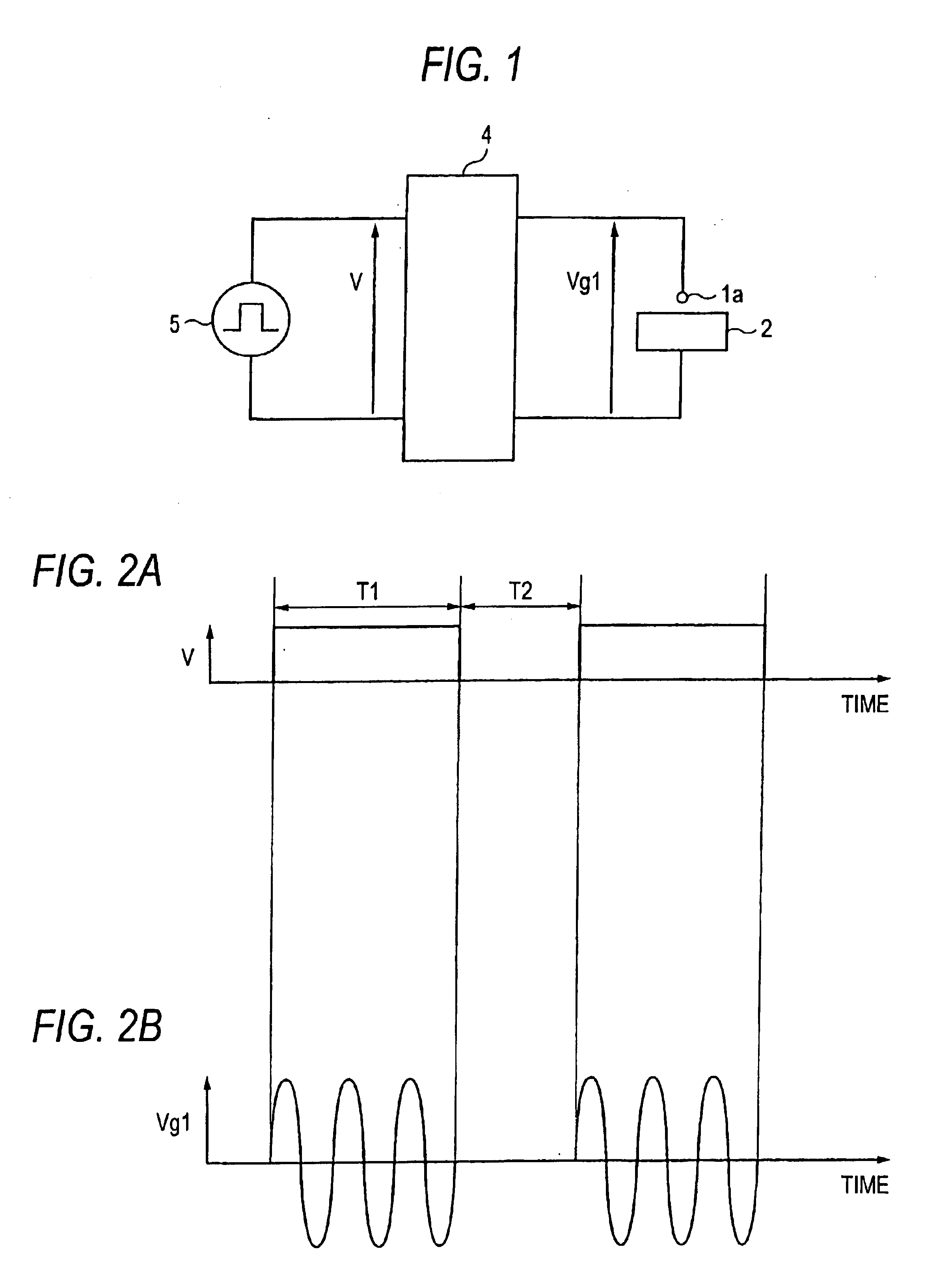
[0040]FIG. 1 is a block diagram of the power supply unit for wire electrical discharge machining in accordance with a first embodiment of the invention. In the drawing, reference numeral 1a denotes a wire electrode; 2, a workpiece; 4, a high-frequency oscillation and amplification circuit; and 5, a pulse power supply. As an intermittent voltage V is inputted from the pulse power supply 5 to the high-frequency oscillation and amplification circuit 4, an ac high-frequency voltage with a voltage Vg1 is applied between the wire electrode 1a and the workpiece 2.

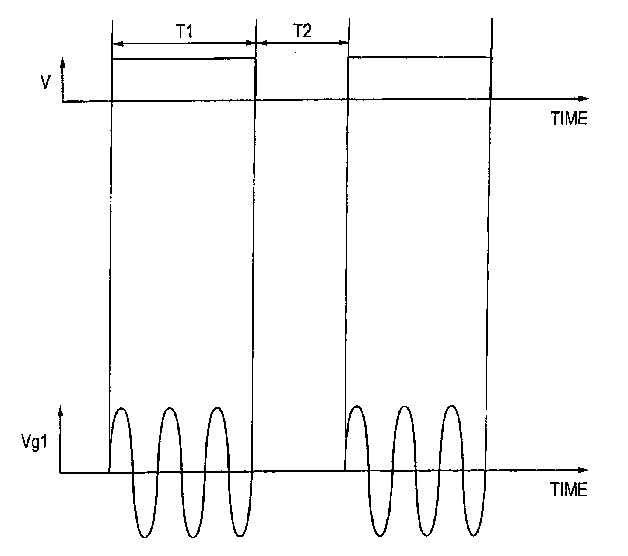
[0041]FIGS. 2A and 2B are conceptual diagrams for explaining the voltage waveform V of the pulse power supply 5 and the bath voltage waveform Vg1 in the power supply unit for wire electrical discharge machining in accordance with the first embodiment of the invention. An ac high-frequency voltage is applied intermittently between the electrode and the workpiece in synchronism with a predetermined time T1 during which a pulse volta...

second embodiment

[0055]FIG. 6 is a circuit diagram of a power supply unit for wire electrical discharge machining in accordance with a second embodiment of the invention. In the drawing, reference numeral 1a denotes the wire electrode; 2, the workpiece; 3, a dc:power supply; 4, the high-frequency oscillation and amplification circuit; and 6, a resistance device. Numerals 7a and 7b denote resistors; 8a and 8b, diodes; and 9a and 9b, FETs. As a predetermined voltage is inputted from the dc power supply 3 to the high-frequency oscillation and amplification circuit 4, an ac high-frequency voltage with a voltage Vg2 is applied between the wire electrode 1a and the workpiece 2. The FETs 9a and 9b in the resistance device 6 connected in parallel to the electrode gap are arranged to be capable of being independently driven by external signals S1 and S2. In addition, the diode 8a is connected in series to the resistor 7a in a direction in which the current flows when the polarity of the wire electrode 1a is ...

third embodiment

[0059]FIG. 8 is a circuit diagram of the power supply unit for wire electrical discharge machining in accordance with a third embodiment of the invention, and the same reference numerals as those in FIG. 6 in accordance with the second embodiment denote identical or corresponding portions. In FIG. 8, reference numeral 5 denotes the pulse power supply; 10, a resistance device; 11, a resistor. Numerals 12a and 12b denote diodes; and 13a and 13b, FETs. As a predetermined voltage is inputted from the dc power supply 3 to the high-frequency oscillation and amplification circuit 4, an ac high-frequency voltage Vg3 is applied between the wire electrode 1a and the workpiece 2. The FETs 13a and 13b in the resistance device 10 connected in parallel to the electrode gap are arranged to be capable of being simultaneously driven by the pulse power supply 5. At the time of the reverse polarity, the current flows across the resistor 11 through the FET 13a and the diode 12b of the FET 13b, while at...


PUM

PropertyMeasurementUnit
Timeaaaaaaaaaa
Timeaaaaaaaaaa
Electric potential / voltageaaaaaaaaaa

Abstract

A power supply unit for wire electrical discharge machining using an ac high-frequency power supply for applying an ac high-frequency voltage between a wire electrode (1a) and a workpiece (2) includes a high-frequency oscillation and amplification circuit (4) and a pulse power supply (5) which is an ac-high-frequency-voltage intermittently supplying unit for effecting the application of the ac high-frequency voltage between the electrode and the workpiece and a pause thereof. In wire electrical discharge machining using this power supply unit for wire electrical discharge machining, it is possible to suppress the vibration of the wire electrode (1a) due tog the electrostatic force acting between the wire electrode (1a) and the workpiece (2), making it possible to improve the straightness accuracy of a machined surface of the workpiece (2) and make surface roughness small.

Description

TECHNICAL FIELD[0001]The present invention relates to improvements in a power supply unit for wire electrical discharge machining and a method of wire electrical discharge machining which are used in wire electrical discharge machining for machining a workpiece by generating electric discharge in an electrode gap between a wire electrode and the workpiece to supply machining electric power to the electrode gap.BACKGROUND ART[0002]As a conventional power supply unit for wire electrical discharge machining for supplying machining electric power between an electrode and a workpiece, it is known that a fine machined surface can be obtained in the workpiece by applying an ac high-frequency voltage between the electrode and the workpiece and generating electric discharge of short time durations at a high frequency of repetition. For example, it is disclosed in JP-A-61-260915 that a machined surface of 1 μm Rmax or less can be obtained by applying an ac high-frequency voltage of 1 MHz to 5...

Claims


Application Information

Patent Timeline
IPC IPC(8): B23H7/04B23H1/02B23H7/00C01F11/18C05D3/02C09C1/02
CPCB23H1/022B23H7/04
Inventor NAKASHIMA, TOSHIOHATTORI, KOUICHIROUUKAI, YOSHIKAZUTANEDA, ATSUSHIGOTO, AKIHIROHASHIMOTO, TAKASHI
Owner MITSUBISHI ELECTRIC CORP
Why Eureka
Try Eureka