
Method of and apparatus for processing a video image

a video image and contrast adjustment technology, applied in the field of video image contrast adjustment, can solve the problems of inconsistent hue values between alternating field video and plant material on the ground, under natural, outdoor conditions, and is not easily detected, so as to enhance the color information of the video image

Inactive Publication Date: 2005-08-16
CNH IND CANADA
View PDF14 Cites 18 Cited by
  • Summary
  • Abstract
  • Description
  • Claims
  • Application Information

AI Technical Summary

Benefits of technology

[0017]An object of the present invention to provide a technique for enhancing the color information in a video image of a scene while adjusting the contrast of the image, the scene being illuminated with varying or non-uniform lighting.

Problems solved by technology

However, plant material on the ground, under natural, outdoor conditions, is not easily detected based on color detection if the detection equipment is a conventional video camera.
As a result, the hue values between alternating fields of video are inconsistent.

Method used


Image

  • Method of and apparatus for processing a video image
  • Method of and apparatus for processing a video image
  • Method of and apparatus for processing a video image

Examples


Embodiment Construction

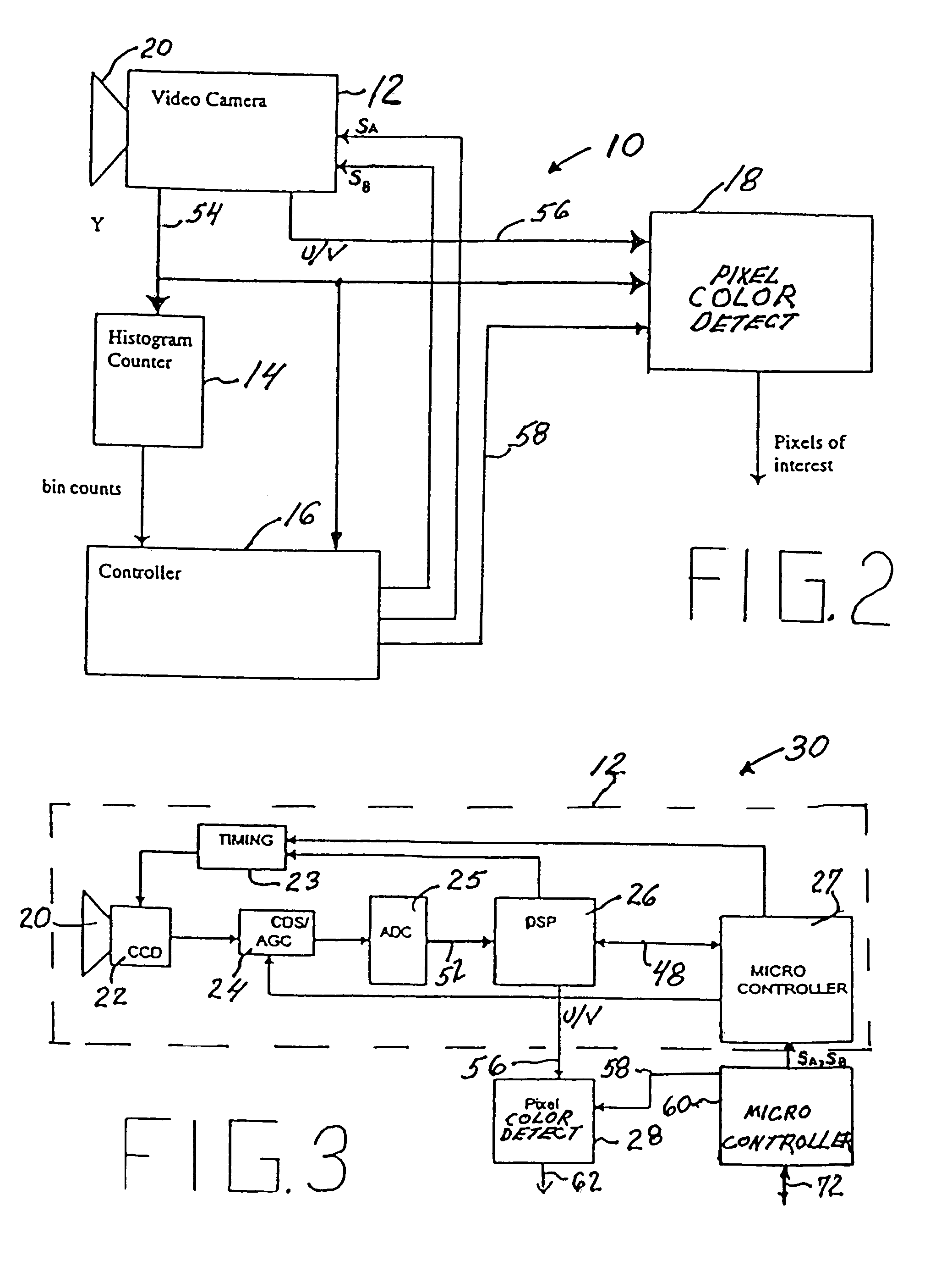
[0033]Referring to FIG. 2, a video system 10 according to the invention comprises a CCD color video camera 12, a histogram counter 14, a micro controller 16 and a pixel color detection circuit 18.

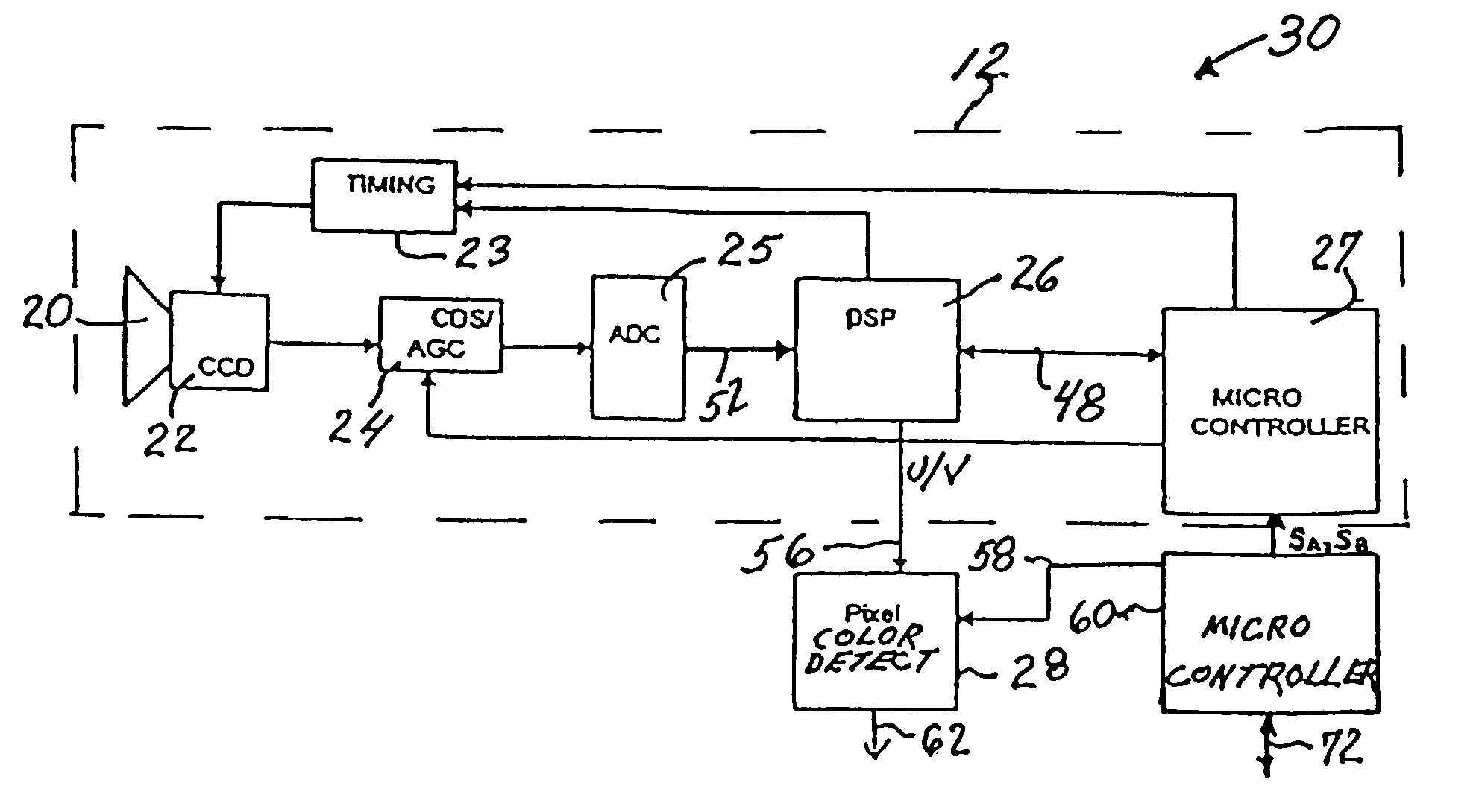
[0034]Camera 12 is a well-known Sony camera and will first be described to provide background for understanding the invention. As shown in FIG. 3, camera 12 comprises a lens 20 for imaging a scene on a Charge Coupled Device (CCD) sensor 22, a timing control and driver circuit 23, a Correlated Double Sampling and Analog Gain Control circuit (CDS / AGC) 24, an analog to digital converter (ADC) 25, and a Digital Signal Processor (DSP) 26. For clarity in explaining the invention, a micro controller 27 is shown separately in FIG. 3 but in actual practice this micro controller is implemented within DSP 26 as shown in FIG. 4.

[0035]Timing control and driver circuit 23 may be a model CXD2408R chip commercially available from Sony Corporation. Circuit 23, in response to commands from micro controller 2...


PUM


Abstract

A color enhancement method for use in a video camera imaging system (10,30) in the context of non-uniform lighting includes an adaptive algorithm (100–110) for developing a shutter speed control signal, analog gain control signal and color balance signals from pixel luminance over one field of video. The control signals developed during one field are used to control the camera (12) during the next field. The speed control signal and analog signal are determined based on the luminance signal obtained in digital form from the video camera, and analyzed over at least one field of video. During one field, the speed control signal and the analog gain signal target dark areas of the image and during the next field they target the bright areas of the image so that, over two fields, every pixel is within a workable range of luminance in at least one of two alternate fields. As the color balance settings for the fields are adjusted according to the exposure settings and the luminance level, consistent hue values are maintained between alternate fields. Additionally, a pixel color detection circuit (18,28) examines each pixel from the video camera (12) to determine whether it is in a color region of interest. The pixel color detection circuit uses a color offset signal, calculated by a controller (16,60) based on the luminance signal during the preceding field. The color offset signal indicates how far from neutral, or white, in the chosen color space, is the chrominance data from the camera. The video camera and pixel color detection circuit may be used to identify weeds or plant material on the ground. A controller (74) is responsive to the pixel color detection circuit and activates one or more spray nozzles ((68,70) when a weed is detected.

Description

RELATED APPLICATIONS[0001]This application incorporates by reference the disclosures of our concurrently filed application Ser. No. 09 / 438,405 entitled Method For Color Detection In Video Images and our U.S. Provisional Application No. 60 / 108,339 filed Nov. 13, 1998.FIELD OF THE INVENTION[0002]The present invention relates to a method and apparatus for adjusting the contrast of a video image in a color video camera. More particularly, the invention provides for contrast adjustment with color gain adjustment in each field of video so that consistent hue values are maintained between fields and the resulting image more closely approximates the dynamic range of the human eye.BACKGROUND OF THE INVENTION[0003]A variety of discrimination systems, operating in a range of circumstances, use color analysis as a basic tool. An example can be found in agriculture, where a green area, such as a weed or other target plant, is to be detected within an area of another color, such as brown soil, in...

Claims


Application Information

Patent Timeline
IPC IPC(8): H04N9/73
CPCH04N5/2353H04N5/243H04N9/735H04N23/76H04N23/73H04N23/88
Inventor CLASSEN, BRIAN J.CHRISTOFF, JORDAN C.
Owner CNH IND CANADA
Learn More