Vaporizer for MOCVD and method of vaporizing raw material solutions for MOCVD

a mocvd and raw material technology, applied in the direction of chemical vapor deposition coating, combustion air/fuel air treatment, refrigeration components, etc., can solve the problems of reducing storage capacitance, reducing yield, and unable to realize in 256 mbits or larger drams, so as to achieve stable feed of raw materials

Inactive Publication Date: 2005-08-16
KANUSHIKI KAISHA WATANABE SHOKO +2
View PDF11 Cites 7 Cited by
  • Summary
  • Abstract
  • Description
  • Claims
  • Application Information

AI Technical Summary

Benefits of technology

[0020]It is therefore an object of the present invention to provide a vaporizer for MOCVD capable of long-term use without causing any clogging or other inconveniences and ensuring a stable feed of raw materials to the reacting section.

Problems solved by technology

Problematic in the development of DRAMs is a reduction in storage capacitance resulting from the miniaturization.
Such three-dimensional structures have disadvantageously given rise to an increase in the stages due to the complicated process and a reduction in the yield due to the increased steps, rendering the realization in 256 Mbits or larger DRAMs difficult.
This technique however has a deficiency that the metal filter may become clogged after several-times vaporizations, making the long-term use difficult.
This technique however entails a problem that the pores may become clogged as a result of several-times operations, rendering it difficult to endure the long-term use.
However, the above prior art has not necessarily met such a demand.

Method used


Image

  • Vaporizer for MOCVD and method of vaporizing raw material solutions for MOCVD
  • Vaporizer for MOCVD and method of vaporizing raw material solutions for MOCVD
  • Vaporizer for MOCVD and method of vaporizing raw material solutions for MOCVD

Examples


embodiment 1

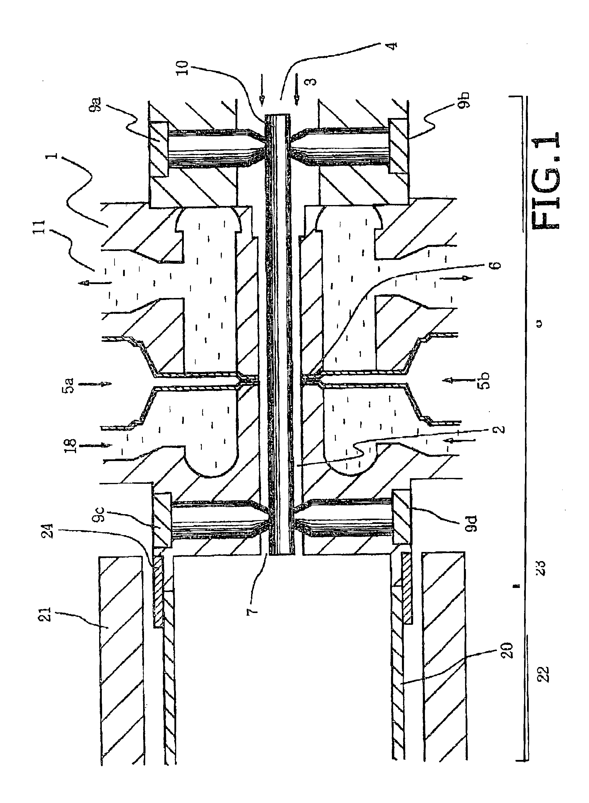
[0038]FIG. 1 illustrates a vaporizer for MOCVD in accordance with embodiment 1.

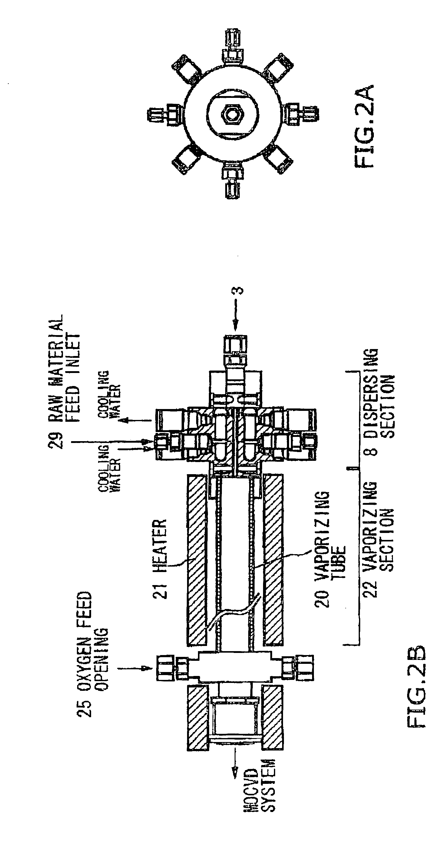
[0039]The vaporizer of this embodiment is constituted of a dispersing section 8 and a vaporizing section 22. The dispersing section 8 comprises a gas passage 2 formed in the interior of a dispersing section body 1 constituting the dispersing section 8, a gas introduction port 4 for introducing a carrier gas 3 under pressure into the gas passage 2, means (a raw material feed opening) 6 for feeding a raw material solution 5 to the carrier gas 3 passing through the gas passage 2, a gas outlet 7 for delivering the carrier gas 3 containing the dispersed raw material solution 5 to the vaporizing section 22, and means (cooling water) 18 for cooling the carrier gas 3 flowing through the gas passage 2. The vaporizing section 22 comprises a vaporizing tube 20 having one end connected to a reaction tube of the MOCVD system and having the other end connected to the gas outlet 7 of the dispersing section 8, and heatin...

embodiment 2

[0074]FIG. 5 illustrates a vaporizer for MOCVD in accordance with embodiment 2.

[0075]In the embodiment 1 the connecting section 23 was also subjected to heating by the heater 21, whereas in this embodiment the heater was provided only around the external periphery of the vaporizing section 22. Instead, cooling means 50 were provided around the external periphery of the connecting section 23 to cool the connecting section 23.

[0076]The others were the same as the embodiment 1.

[0077]In this embodiment, better coincidence was obtained than in the case of the embodiment 1 between detected products and products in the reaction formula examined on the basis of the reaction theory.

[0078]The result of measurement of the amount of adhesion of carbides on the external surface of the dispersing section body 1 toward the gas outlet 7 was about one third the amount of adhesion of carbides in the case of the embodiment 1.

embodiment 3

[0079]FIG. 6 illustrates a vaporizer for MOCVD in accordance with embodiment 3.

[0080]in this embodiment, the interior of the connecting section 23 has a tapered portion 51 with larger inner diameters from the dispersing section 8 toward the vaporizing section 22, Such a tapered portion 51 serves to eliminate any dead zones and contributes to the prevention of possible residence of the raw material.

[0081]The others were the same as the embodiment 1.

[0082]In this embodiment, better coincidence was obtained than in the case of the embodiment 2 between detected products and products in the reaction formula examined on the basis of the reaction theory.

[0083]Measurement of the amount of adhesion of carbides on the external surface of the dispersing section body 1 toward the gas outlet 7 resulted in substantially no adhesion of carbides.


PUM

PropertyMeasurementUnit
flow velocityaaaaaaaaaa
relative dielectric constantsaaaaaaaaaa
pressureaaaaaaaaaa

Abstract

Disclosed is a vaporizer constituted of a dispersing section 8 and a vaporizing section 22. The dispersing section 8 comprises a gas introduction port 4 for introducing a carrier gas 3 under pressure into a gas passage, means for feeding raw material solutions 5a and 5b to the gas passage, and a gas outlet 7 for delivering the carrier gas containing the raw material solutions to the vaporizing section 22. The vaporizing section 22 comprises a vaporizing tube 20 having one end connected to a reaction tube of the MOCVD system and having the other end connected to the gas outlet 7 of the dispersing section 8, and heating means for heating the vaporizing tube 20. The vaporizing section 22 serves to heat and vaporize the raw material solution containing carrier gas 3 delivered from the dispersing section 8. The dispersing section 8 includes a dispersing section body 1 having a cylindrical hollow portion, and a rod 10 having an outer diameter smaller than the inner diameter of the cylindrical hollow portion. The rod 10 has a spiral groove 60 formed in the external periphery closer to the vaporizing section 22, the rod 10 being inserted into the cylindrical hollow portion.

Description

CONTINUATION APPLICATION[0001]This application is a divisional application, which hereby claims the benefit under Title 35, United States Code §119 (e) U.S. Pat. No. 6,540,840 application Ser. No. 09 / 488,764, filed on Jan. 21, 2000 now U.S. Pat. No. 6,540,840.BACKGROUND OF THE INVENTION[0002]1. Field of the Invention[0003]The present invention relates to a vaporizer for MOCVD and a method of vaporizing raw material solutions for MOCVD.[0004]2. Description of the Related Arts[0005]Problematic in the development of DRAMs is a reduction in storage capacitance resulting from the miniaturization. Any measures are needed since the capacitance has to be level with that in the precedent generation from the viewpoint of software errors or the like. As a measure for this, increase in the capacitor area has been aimed at by introducing a three-dimensional structure referred to as a stack structure or a trench structure for cell structures exceeding 4M in addition to the planer structure for 1M...

Claims


Application Information

Patent Timeline
Patent Type & Authority Patents(United States)
IPC IPC(8): C23C16/448C23C16/40H01L21/31H01L21/8242H01L27/108
CPCC23C16/409C23C16/4486
Inventor TODA, MASAYUKIKUSUHARA, MASAKIDOI, MIKIOUMEDA, MASARUFUKAGAWA, MITSURUKANNO, YOICHIUCHISAWA, OSAMUYAMAMOTO, KOHEIMEGURO, TOSHIKATU
Owner KANUSHIKI KAISHA WATANABE SHOKO
Why Eureka
Try Eureka