Fully integrated low noise multi-loop synthesizer with fine frequency resolution for HDD read channel and RF wireless local oscillator applications

a multi-loop, fully integrated technology, applied in the field of frequency synthesizers, can solve the problems of phase noise, multiple frequency step sizes, and generation of spurious signals

Inactive Publication Date: 2005-08-16
TEXAS INSTR INC
View PDF9 Cites 39 Cited by
  • Summary
  • Abstract
  • Description
  • Claims
  • Application Information

AI Technical Summary

Benefits of technology

[0028]One exemplary advantage of the multi-loop synthesizer is that the requirements are divided between two loops and the translation loop, which combines the outputs of the two loops with a unity multiplication factor. The fine tune loop provides the small frequency step size, yet the phase noise of this loop does not significantly affect the final output. The coarse tune loop provides low phase noise performance without significantly affecting the frequency step size. The phase noise of the coarse tune loop inside the translation loop bandwidth dominates the other phase noise sources. The low multiplication factor and wide bandwidth allows phase noise to be minimized in the coarse tune loop.
[0038]Advantageously, by allowing the natural discharge of the integrating capacitor in the active loop filter to control the frequency sweep, switching discontinuities normally associated with switching transients when lock occurs are avoided. Other techniques that switch components in and out of the circuit at the lock point produce a transient that can cause the loop to lose lock.

Problems solved by technology

In the production of this high frequency, conventional synthesizers use a high multiplication of the original input reference signal, but as a byproduct, also detrimentally multiply the frequency step size, the phase noise, and generate spurious signals.

Method used


Image

  • Fully integrated low noise multi-loop synthesizer with fine frequency resolution for HDD read channel and RF wireless local oscillator applications
  • Fully integrated low noise multi-loop synthesizer with fine frequency resolution for HDD read channel and RF wireless local oscillator applications
  • Fully integrated low noise multi-loop synthesizer with fine frequency resolution for HDD read channel and RF wireless local oscillator applications

Examples


Embodiment Construction

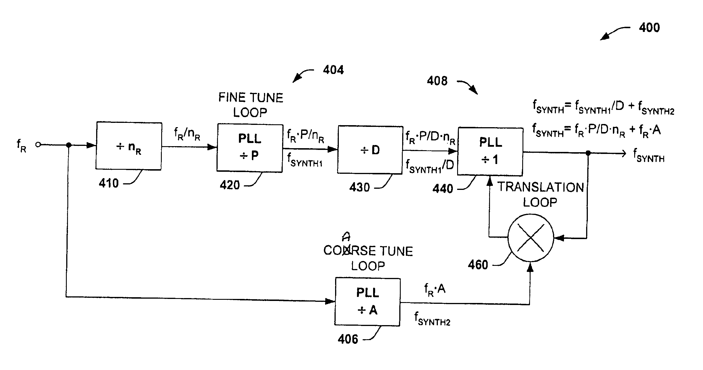
[0056]The present invention will now be described with reference to the drawings, wherein like reference numerals are used to refer to like elements throughout. The present invention relates to an exemplary low phase noise multi-loop synthesizer for producing an RF frequency used, for example, as a local oscillator for a read channel in a hard disk drive and for RF wireless communications applications. The multi-loop synthesizer output frequency can be programmed in fine steps, and frequency modulated to provide broad bandwidth into the microwave frequency range and may be fully integrated along with an internal VCO on a semiconductor chip. The specific arrangement of three (3) PLL loops as well as components within the multi-loop synthesizer and the application of a translation loop, permits a particularly low phase noise RF output with a fine frequency step size in a small, low power solution.

[0057]FIG. 7 shows an exemplary low phase noise multi-loop synthesizer according to the p...


PUM


Abstract

A low noise multi-loop radio frequency synthesizer receives an input reference signal having a frequency fR, into a fine tune PLL and a coarse tune PLL. The fine tune PLL outputs a fine tune signal with a frequency fR□P, P beings an integer, while the coarse tune PLL outputs a coarse tune signal with frequency fR□A, where A is an integer. A translation PLL has a unity multiplication factor and is driven by the fine tune signal output. The frequency synthesizer has a Gilbert cell double balanced mixer coupled between the coarse tune and the translation PLLs, the Gilbert cell mixer combining the coarse tune signal and the output signal of the translation PLL and coupling the mixed signal into the translation PLL. The translation loop outputs a signal with a frequency proportional to the linear sum of the coarse tune signal and the fine tune signal.

Description

TECHNICAL FIELD OF INVENTION[0001]The present invention relates generally to the field of frequency synthesizers, and more specifically to a low phase noise multi-loop RF synthesizer, operable to generate a frequency which can be programmed in fine steps, and frequency modulated to provide broad bandwidth into the microwave frequency range and which may be fully integrated on a semiconductor chip.BACKGROUND OF THE INVENTION[0002]The frequency synthesizer is commonly used in radio frequency devices to provide generation of local oscillator (LO) high frequency signals. Applications include, for example, the read channel in a hard disk drive, and for RF wireless communications such as cellular and digital cordless telephone local oscillator applications. Several of these applications require low phase noise and small frequency steps of the frequency synthesizer.[0003]The read channel of a hard disk drive, for example, requires a synthesizer to generate clock frequencies of 180-500 MHz ...

Claims


Application Information

Patent Timeline
Patent Type & Authority Patents(United States)
IPC IPC(8): H03L7/08H03L7/12H03L7/16H03L7/23
CPCH03L7/12H03L7/23
Inventor GOLDMAN, STANLEY J.
Owner TEXAS INSTR INC
Why Eureka
Try Eureka