
Attachment system for coupling combustor liners to a carrier of a turbine combustor

a technology of combustor and carrier, which is applied in the direction of machines/engines, mechanical equipment, light and heating equipment, etc., can solve the problems of affecting reducing the service life of the turbine engine, so as to reduce the amount of time

Inactive Publication Date: 2005-08-23
SIEMENS ENERGY INC
View PDF21 Cites 32 Cited by
  • Summary
  • Abstract
  • Description
  • Claims
  • Application Information

AI Technical Summary

Benefits of technology

[0007]This invention relates to a system for attaching liners to a carrier for creating an inner surface of a combustor of a turbine engine. The combustor may be, but is not limited to, an annular combustor. The system utilizes both hot side and cold side connectors while substantially eliminating the amount of time typically associated with removing cold side connectors. An exemplary annular combustor may be formed from at least two carriers, which may be an inner carrier and an outer carrier. The inner and outer carriers may form a combustor cavity having a generally toroidal shape. Inner liners may be attached to the inner carrier to form an inner liner surface, and outer liners may be attached to the outer carrier to form an outer liner surface. The inner carrier and its associated inner liners may be configured to fit inside a cavity defined by the outer liner surface formed by the outer liners to complete an annular combustor cavity.
[0012]By coupling the inner liners to the inner carrier in this manner, the number of connectors susceptible to loosening and passing downstream into a turbine blade assembly are substantially reduced. In addition, by coupling the inner liners to the carrier in this manner, the inner liners may be removed and replaced from within the combustor cavity. Thus, removal of the inner liners coupled to the inner carrier using connectors actuated on the cold side of the combustor does not necessitate removal of an engine casing and other related engine components shrouding the cold side to decouple the connectors. Rather, the cold side connectors may be tightened or loosened, or both, by accessing the connectors from the hot side through one or more access ports in the inner carrier.

Problems solved by technology

The removable liners are exposed to extreme heat during operation, which often causes distortions and failure in liners.
However, spring clips often suffer from relaxation and creep after being exposed to high temperatures commonly found in a combustor chamber, which can result in loss of clamp force in the clips.
As a result, spring clips and liners can be liberated during operation of a combustor and cause substantial damage to a turbine engine.
While liners attached to a carrier in this manner may be removed easily, this method of attachment has disadvantages and risks.
For instance, should the bolts loosen during operation, the bolts pose a threat of becoming disengaged from the carrier and traveling downstream into turbine blade assemblies.
In addition, the bolts are exposed to hot gases in the combustor chamber and consequently must be cooled and made from expensive alloys.
Air supplied from the compressor of the turbine combustor is often used to cool the bolts; however, use of compressor supplied air increases nitrous oxide emissions and degrades turbine combustor performance.
However, a significant disadvantage of the cold side bolted method is the amount of time needed to access the bolts to remove and replace the liners.
Instead, the bolts typically may only be accessed after an engine casing has been lifted, which may take hours or weeks.

Method used


Image

  • Attachment system for coupling combustor liners to a carrier of a turbine combustor
  • Attachment system for coupling combustor liners to a carrier of a turbine combustor
  • Attachment system for coupling combustor liners to a carrier of a turbine combustor

Examples


Embodiment Construction

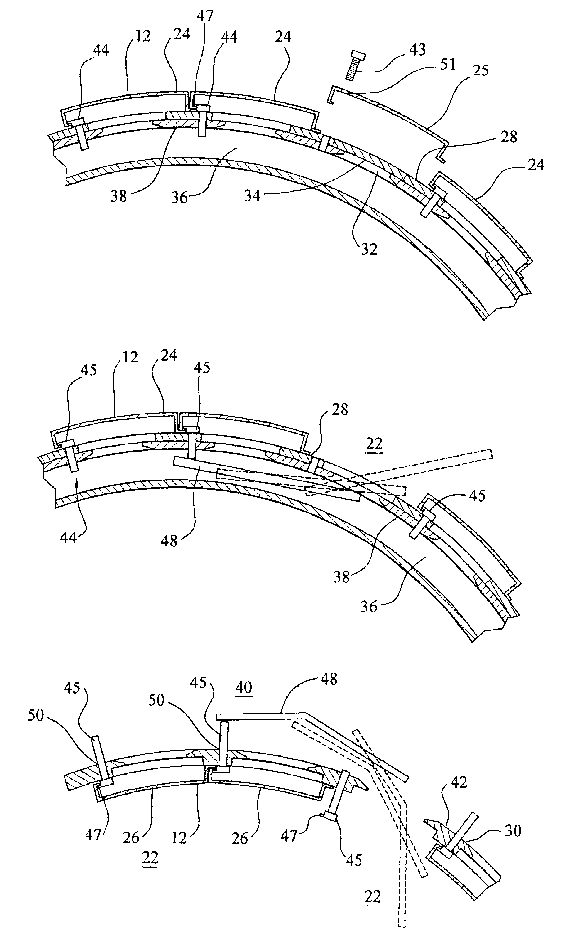
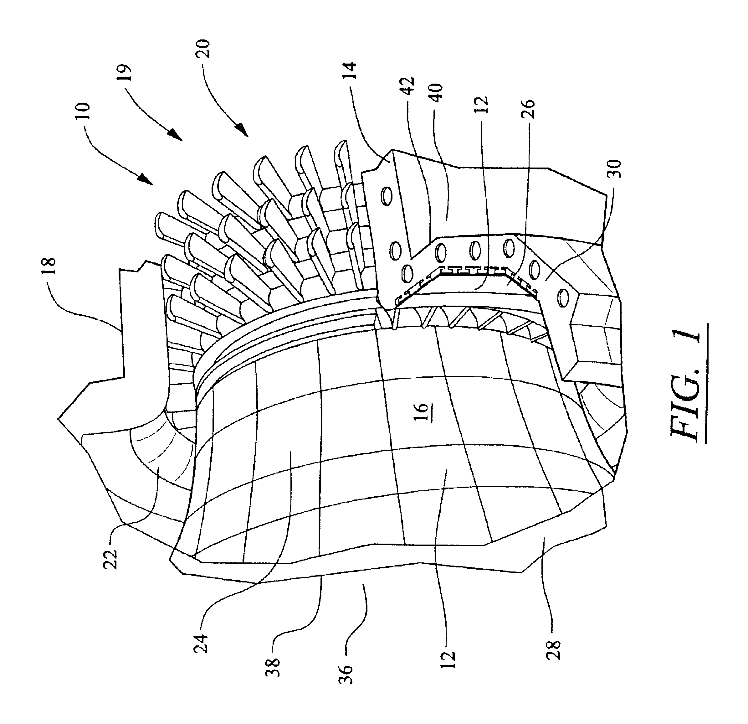
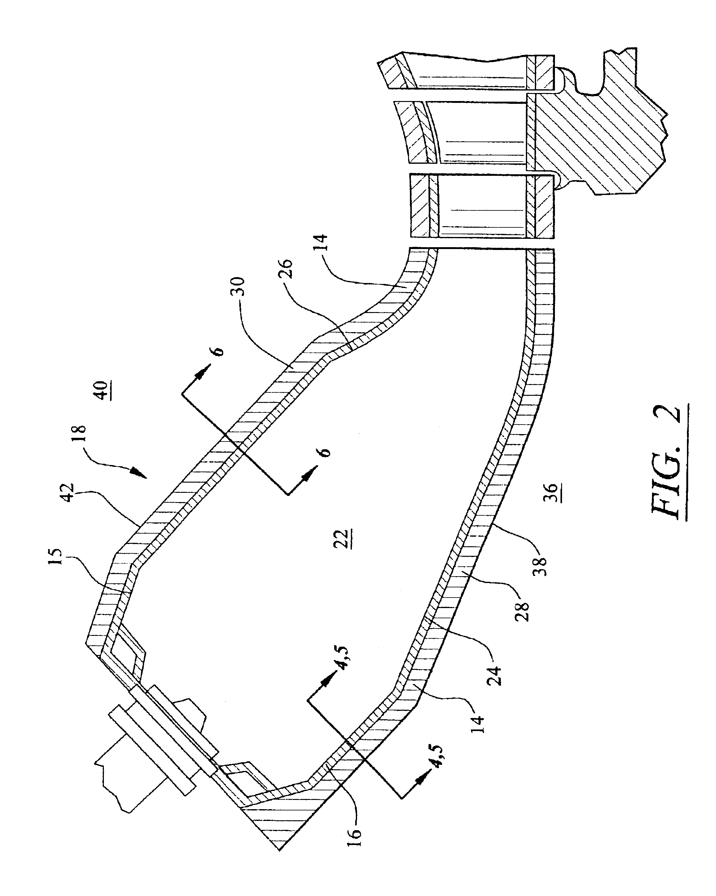
[0023]This invention is directed to attachment system 10 for attaching liners 12 to a carrier 14 to form surfaces 16 of a combustor, such as an annular combustor 18 of a turbine engine 20, illustrated herein as an example. Turbine engine 20 may be any turbine engine having a combustor. Annular combustor 18 may be configured to receive a mixture of fuel and compressed air and to ignite the mixture. Annular combustor 18 may also be configured to pass hot combustion gases to a turbine blade assembly 19. Annular combustor 18 may be formed from a generally toroidal shaped combustor cavity 22, which may be formed from one or more inner liners 24 and one or more outer liners 26. Inner and outer liners 24 and 26 may have numerous configurations. However, in at least one embodiment, inner and outer liners 24 and 26 may be formed from a metallic or ceramic material, and each may be configured to have a generally square or rectangular outer shape.

[0024]Inner liners 24 may be coupled to an inne...


PUM

PropertyMeasurementUnit
temperaturesaaaaaaaaaa
timeaaaaaaaaaa
shapeaaaaaaaaaa

Abstract

A system for attaching liners to a carrier for forming inner surfaces of turbine combustor. The system may include one or more liners attached to a carrier using connectors engaged to the carrier on a cold side of the liner and may include one or more liners attached to the carrier using connectors engaged to a hot side of the liners. The carrier may include one or more access ports for accessing from the hot side connectors engaged to the carrier on the cold side. In at least one embodiment, the system may include attaching all liners, except for one liner, to a carrier using connectors coupled to the carrier on the cold side and may include attaching the one liner to the carrier using connectors coupled to the carrier on the hot side.

Description

FIELD OF THE INVENTION[0001]This invention is directed generally to turbine engines, and more particularly to attachment systems for coupling liners to a carrier of a turbine engine combustor.BACKGROUND[0002]Gas turbine combustors generally may be formed from annular combustors or can combustors. Annular combustors include a combustor chamber that is formed from a plurality of removable liners. The removable liners are exposed to extreme heat during operation, which often causes distortions and failure in liners. Thus, the liners are replaced at regular intervals to prevent such failure from occurring during operation.[0003]The liners are often removably coupled to a carrier, which forms the support structure of the combustor, using either spring clips or bolted configurations. Spring clips couple liners to each other and to the carrier of a combustor. However, spring clips often suffer from relaxation and creep after being exposed to high temperatures commonly found in a combustor ...

Claims


Application Information

Patent Timeline
Patent Type & Authority Patents(United States)
IPC IPC(8): F23R3/60F23R3/00F23M5/00F23M5/04
CPCF23M5/04F23R3/002F23R3/60F23R3/007Y10T29/49346
Inventor GLESSNER, JOHNGULATI, ANIL
Owner SIEMENS ENERGY INC
Features
  • Generate Ideas
  • Intellectual Property
  • Life Sciences
  • Materials
  • Tech Scout
  • Unparalleled Data Quality
  • Higher Quality Content
  • 60% Fewer Hallucinations
Learn More