
Chemical agent detector

a detector and chemical agent technology, applied in the direction of generators/motors, instruments, mechanical means, etc., can solve the problems of unwanted harmonics and add to the overall noise of the rf system, and achieve the effects of high sensitivity, low power consumption, and fast response tim

Inactive Publication Date: 2005-08-23
CONSTELLATION TECH
View PDF9 Cites 12 Cited by
  • Summary
  • Abstract
  • Description
  • Claims
  • Application Information

AI Technical Summary

Benefits of technology

"The present invention is an improved chemical agent detector that uses a plurality of SAW sensors and a pressure / differential manifold to support the sensors and reduce RF noise. A pump is used to draw an ambient air sample into the manifold and expel it through an air channel. Each SAW sensor has its own unique arrangement of \"vias\" to reduce RF noise and improve sensitivity. An RF multiplexor is used to allow only one SAW sensor to pass through at a time, ensuring that the microprocessor always knows which sensor signal it is receiving. The SAW sensors are down converted and sent to the microprocessor for analysis and detection. The invention has fast response time, high sensitivity, low power usage, compact size, and reduced weight with minimal noise. It also has ample bandwidth and tuning capabilities to allow for the detection of a wide variety of chemical agents."

Problems solved by technology

Of course unwanted harmonics can add overall noise to the RF system which can effect the sensitivity and response time of the chemical agent detector.

Method used


Image

  • Chemical agent detector
  • Chemical agent detector
  • Chemical agent detector

Examples


Embodiment Construction

[0026]Throughout the following detailed description, the same reference numerals refer to the same elements in all figures.

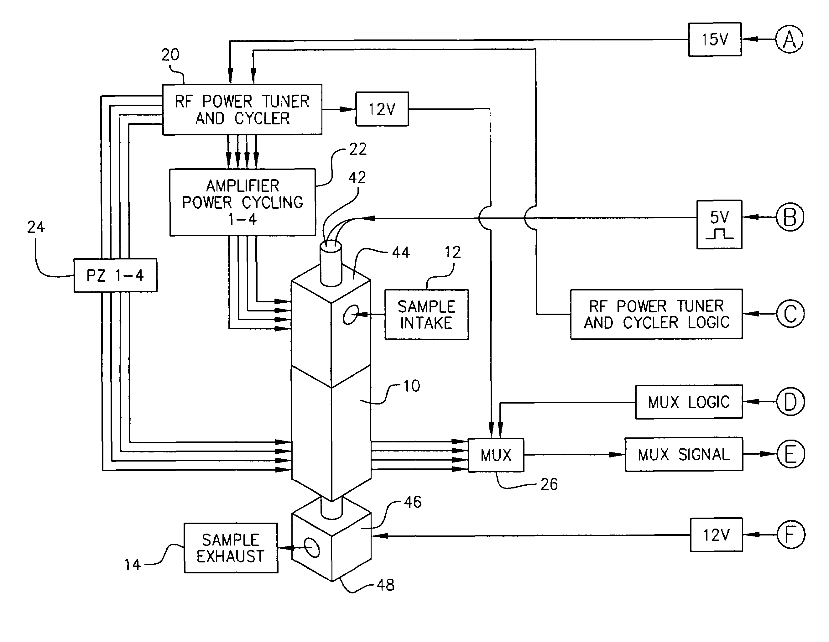
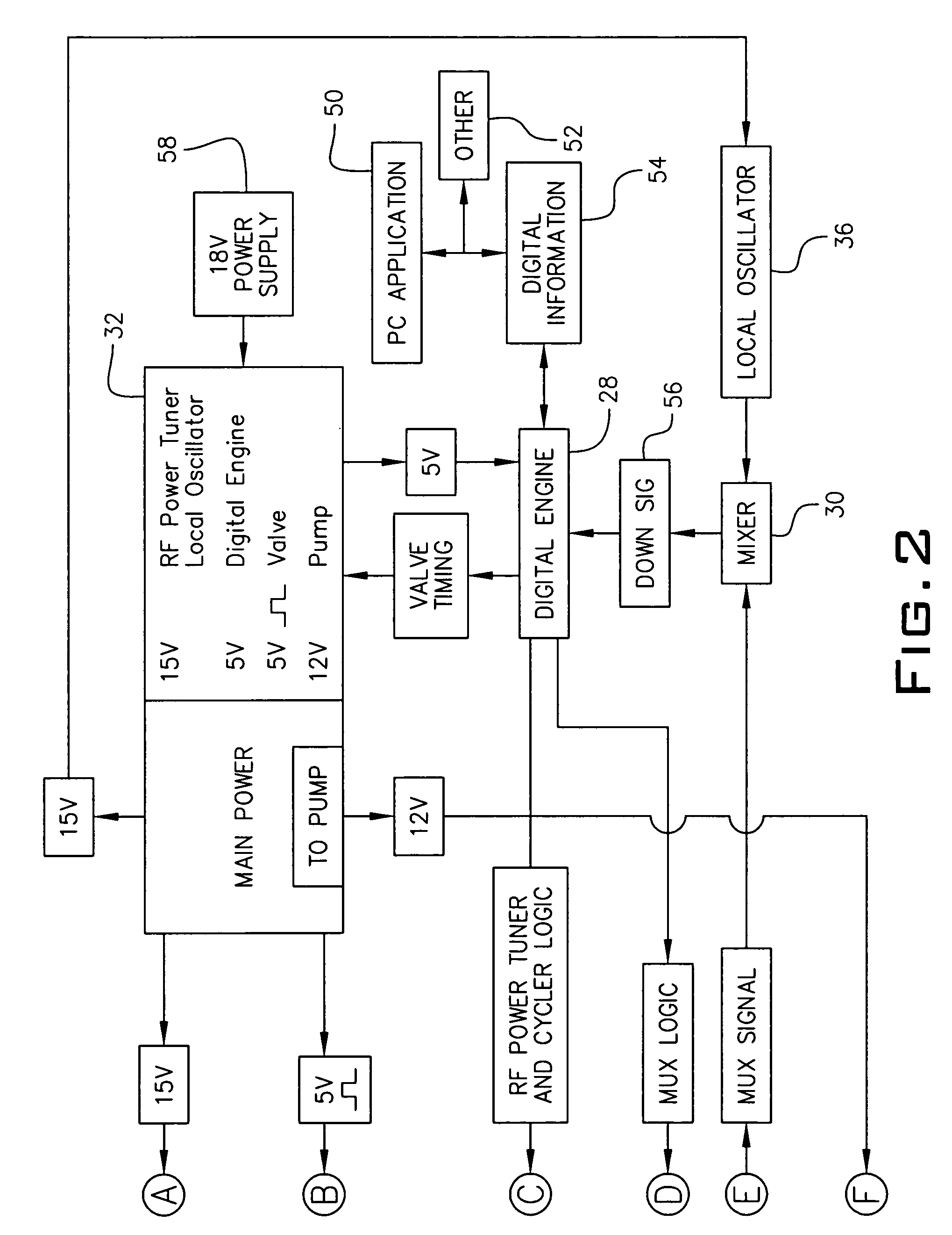
[0027]Referring to FIGS. 1 and 2, a block diagram is shown illustrating the major components of a chemical agent detector of the present invention. In its preferred embodiment, the chemical agent detector of the present invention is enclosed within a small table-top box. However, nothing herein limits that the detector be miniaturized into a small hand-held unit, a pocket sized unit, or even a wristwatch sized unit. And for that matter, nothing herein limits the detector from being a large stand alone mounted within in a building or incorporated within a ventilation system or HVAC system of any sized facility.

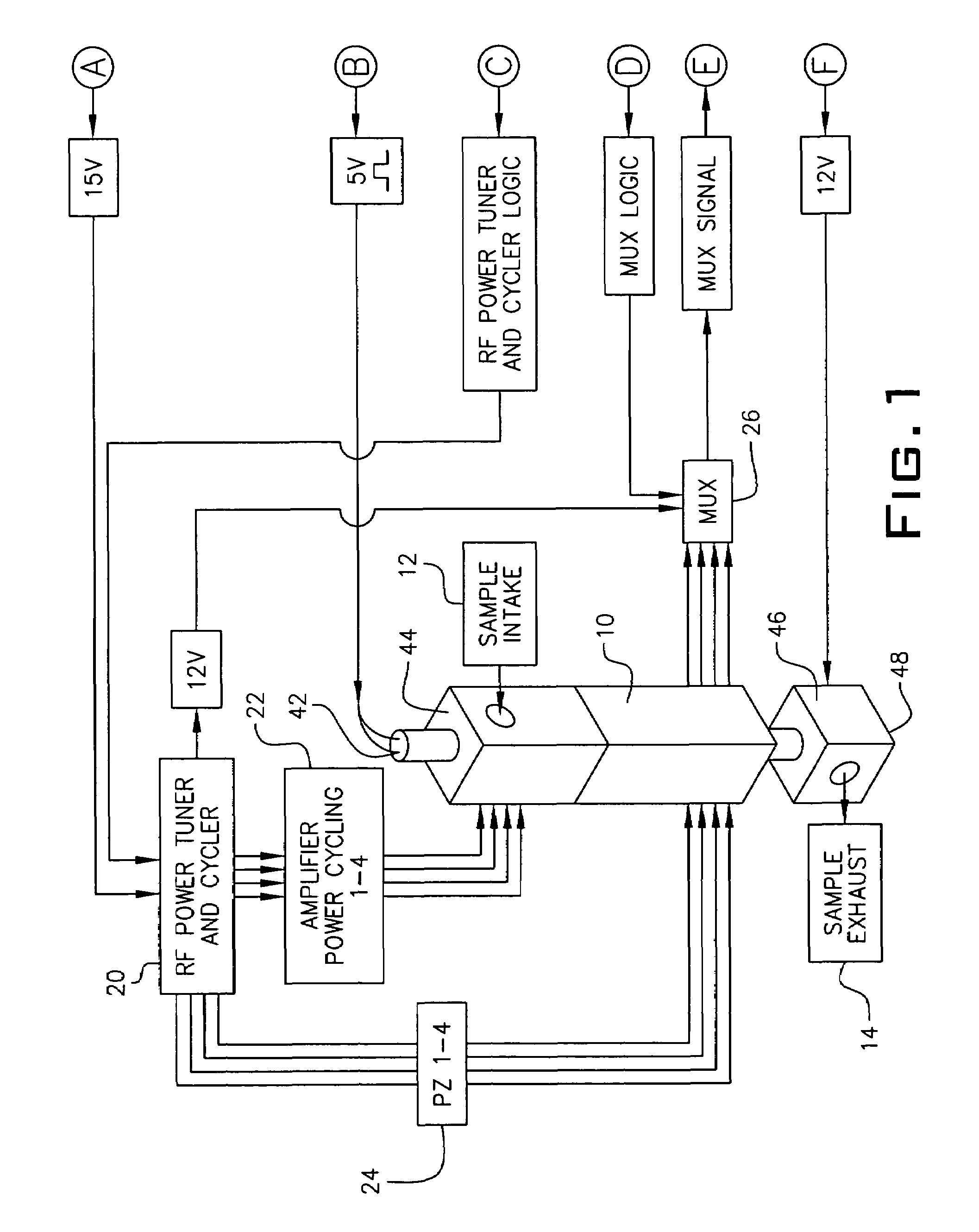
[0028]FIG. 1 illustrates a first part of the block diagram and FIG. 2 illustrates a second part of the block diagram. The block diagrams of FIGS. 1 and 2 are broken apart onto two sheets since the entire block diagram would not fit onto a single sheet. It i...


PUM

PropertyMeasurementUnit
frequencyaaaaaaaaaa
frequenciesaaaaaaaaaa

Abstract

A chemical agent detector utilizing surface acoustic wave (SAW) sensors for detecting the presence of a multitude of chemical agents by sampling ambient air is provided. A pressure-differential manifold having an air intake port, an exhaust port, a valve and a pump is used to draw the ambient air into the manifold to be tested. A plurality of SAW sensors mounted on sensor driver boards which are in turn mounted on the manifold come into contact with the ambient air sample. Each SAW sensor is coated with a substance that has an affinity for detecting a particular chemical agent. Each SAW sensor driver board generates a continuous RF signal which emits a frequency shift if a particular chemical agent is detected. A power cycler module turns each sensor driver board on and off such that only one sensor driver board is powered-on at a given point in time. An RF multiplexor receives the continuous RF signals generated by the sensor driver boards and outputs one of the RF signals to a microprocessor based upon a timing signal generated by the microprocessor. The microprocessor interprets the frequency shift as the detection of a chemical agent and provides an alarm that a particular chemical agent has been detected.

Description

GOVERNMENT LICENSE RIGHTS[0001]This invention was made with U.S. Government support under contract or grant DTRA02-99-C-0187 awarded by the Defense Treat Reduction Agency. The U.S. Government has certain rights in the invention.BACKGROUND OF THE INVENTION[0002]1. Field of the Invention[0003]This invention relates to a chemical agent detector. More particularly, it relates to a device used for the detection of chemical agents, vapors and gases which utilizes a plurality of surface acoustic wave (SAW) based sensors in a microcontroller circuit for its sensing and detection functions.[0004]2. Background of the Prior Art[0005]Surface Acoustic Wave (or SAW) based sensors are known in the prior art. SAW sensor devices can be used in the detection of chemical agents, vapors and gases, aerosols and fluids. The detection of chemical agents which may be hazardous to the environment and to the health of living organisms has become very important. The safeguarding of workers in a factory or tha...

Claims


Application Information

Patent Timeline
Patent Type & Authority Patents(United States)
IPC IPC(8): G01N29/02G01N7/00G01N29/24G01N33/00
CPCG01N29/022G01N29/24G01N33/0031G01N2291/0256G01N2291/0423G01N2291/106
Inventor MANOOSINGH, LANE L.
Owner CONSTELLATION TECH
Learn More