Control system for positioning of marine seismic streamers

a technology of positioning system and streamer, which is applied in underwater equipment, vessel construction, instruments, etc., can solve the problems of reducing the efficiency of current 3d seismic survey operations by between 5 and 10%, affecting the accuracy of streamer positioning, and virtually impossible for this type of system to closely regulate horizontal positions. , to achieve the effect of reducing the need for in-fill shooting, reducing the chance of streamer tangling, and being more controlled

Inactive Publication Date: 2005-08-23
SCHLUMBERGER TECH CORP
View PDF3 Cites 149 Cited by
  • Summary
  • Abstract
  • Description
  • Claims
  • Application Information

AI Technical Summary

Benefits of technology

[0010]An advantage of the present invention is that the position of the streamer may be better controlled, thereby reducing the need for in-fill shooting, reducing the chance of streamer tangling, and reducing the time needed to turn the seismic survey vessel.
[0011]Another advantage of the present invention is that noise in marine seismic data associated with streamer position over-correction and streamer positioning errors can be significantly reduced.
[0012]The present invention provides methods and apparatus for controlling the positions of marine seismic streamers in an array of such streamers being towed by a seismic survey vessel, the streamers having respective streamer posit

Problems solved by technology

It is estimated that horizontal out-of-position conditions reduce the efficiency of current 3D seismic survey operations by between 5 and 10%, depending on weather and current conditions.
While incidents of tangling adjacent streamers are relatively rare, when they do occur they invariably result in prolonged vessel downtime.
While this method greatly simplifies the circuitry needed within the bird itself, it is virtually impossible for this type of system to closely regulate the horizontal positions of the bird

Method used


Image

  • Control system for positioning of marine seismic streamers
  • Control system for positioning of marine seismic streamers
  • Control system for positioning of marine seismic streamers

Examples


Embodiment Construction

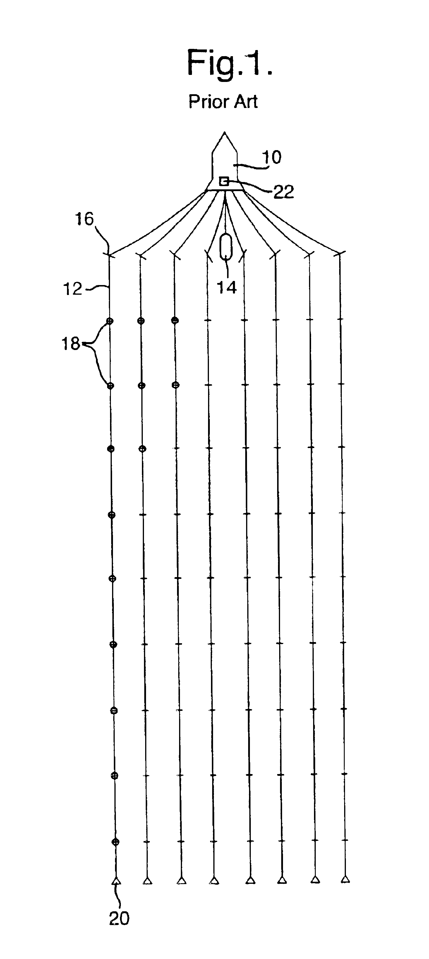
[0018]In FIG. 1, a seismic survey vessel 10 is shown towing eight marine seismic streamers 12 that may, for instance, each be 3000 meters in length. The outermost streamers 12 in the array could be 700 meters apart, resulting in a horizontal separation between the streamers of 100 meters in the regular horizontal spacing configuration shown. A seismic source 14, typically an airgun or an array of airguns, is also shown being towed by the seismic survey vessel 10. At the front of each streamer 12 is shown a deflector 16 and at the rear of every streamer is shown a tail buoy 20. The deflector 16 is used to horizontally position the end of the streamer nearest the seismic survey vessel 10 and the tail buoy 20 creates drag at the end of the streamer farthest from the seismic survey vessel 10. The tension created on the seismic streamer by the deflector 16 and the tail buoy 20 results in the roughly linear shape of the seismic streamer 12 shown in FIG. 1.

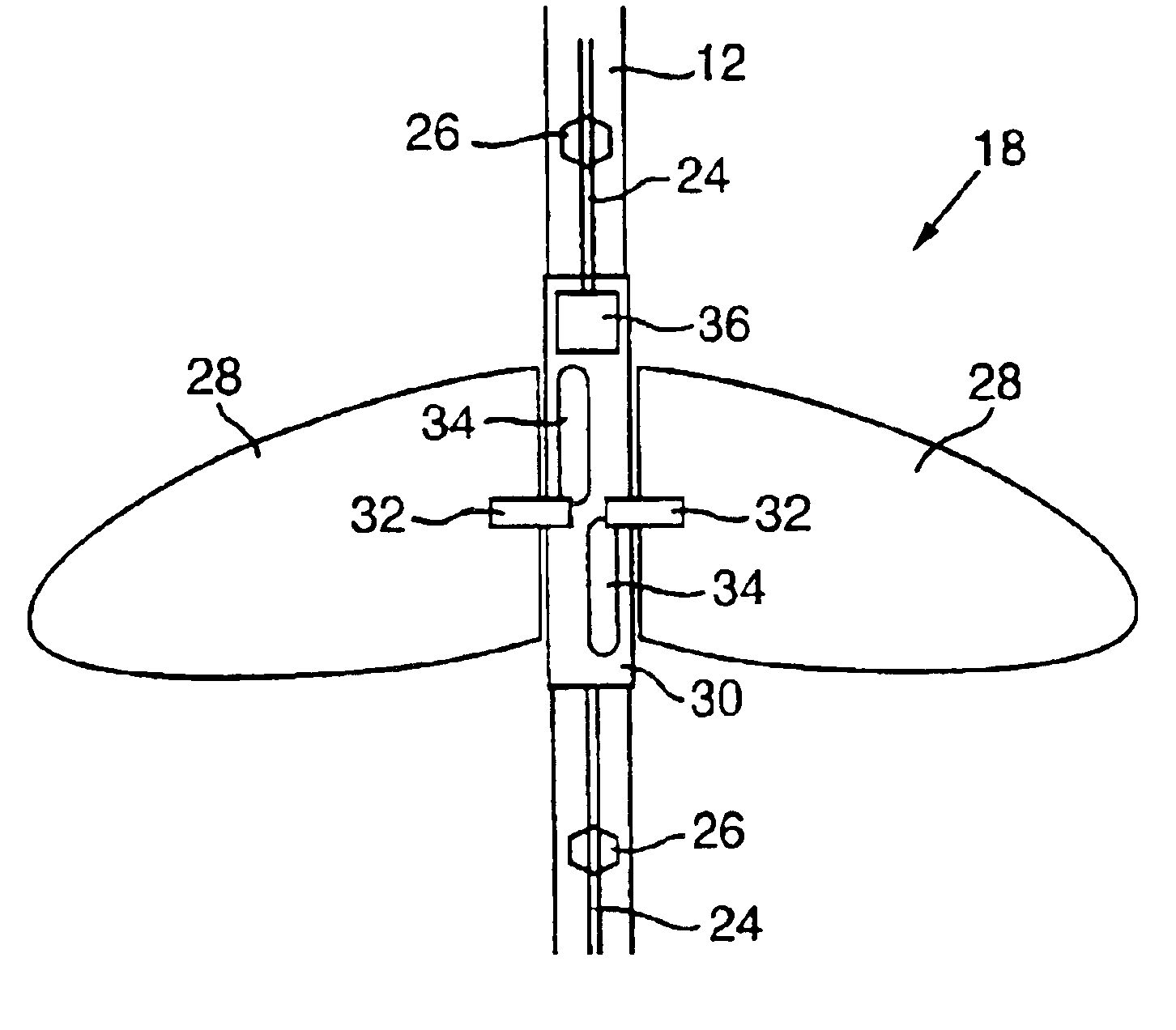
[0019]Located between the deflect...


PUM


Abstract

A method of controlling a streamer positioning device (18) configured to be attached to a marine seismic streamer (12) and towed by seismic survey vessel (10) and having a wing and a wing motor for changing the orientation of the wing. The method includes the steps of: obtaining an estimated velocity of the streamer positioning device, calculating a desired change in the orientation of the wing using the estimated velocity of the streamer positioning device, and actuating the wing motor to produce the desired change in the orientation of the wing. The invention also involves an apparatus for controlling a streamer positioning device including means for obtaining an estimated velocity of the streamer positioning device, means for calculating a desired change in the orientation of the wing using the estimated velocity of the streamer positioning device, and means for actuating the wing motor to produce the desired change in the orientation of the wing.

Description

BACKGROUND OF THE INVENTION[0001]This invention relates generally to systems for controlling seismic data acquisition equipment and particularly to a system for controlling a marine seismic streamer positioning device.[0002]A marine seismic streamer is an elongate cable-like structure, typically up to several thousand meters long, which contains arrays of seismic sensors, known as hydrophones, and associated electronic equipment along its length, and which is used in marine seismic surveying. In order to perform a 3D marine seismic survey, a plurality of such streamers are towed at about 5 knots behind a seismic survey vessel, which also tows one or more seismic sources, typically air guns. Acoustic signals produced by the seismic sources are directed down through the water into the earth beneath, where they are reflected from the various strata. The reflected signals are received by the hydrophones, and then digitized and processed to build up a representation of the subsurface geo...

Claims


Application Information

Patent Timeline
IPC IPC(8): B63B21/56B63B21/66G01V1/38
CPCB63B21/66G01V1/3826G01V1/38G01V1/3817G01V1/20
Inventor HILLESUND, OYVINDBITTLESTON, SIMON HASTINGS
Owner SCHLUMBERGER TECH CORP
Why Eureka
Try Eureka