Engine control system for internal combustion engines

a technology of engine control and internal combustion engine, which is applied in the direction of electric control, speed sensing governor, machines/engines, etc., can solve the problems of reducing or increasing the engine speed, and the input from the operator-commanded engine speed and the actual engine speed, and affecting the operation of the engine. , to achieve the effect of dampening the response of the engine control system and simple adjustment of the engine control

Inactive Publication Date: 2005-08-23
TECUMSEH POWER
View PDF13 Cites 15 Cited by
  • Summary
  • Abstract
  • Description
  • Claims
  • Application Information

AI Technical Summary

Benefits of technology

[0016]Advantageously, the present engine control system for internal combustion engines provides operator setting, detection, and adjustment of engine speeds using electrical components and electrical signals in the place of certain mechanical components which had typically been used in known systems. The electrical and other components of the present engine control system reliably transmit engine control signals and provide for simple adjustment of engine control and dampening of the response of the engine control system to changes in the engine speed.

Problems solved by technology

However, driving a variable load may reduce or increase the engine speed from the commanded setting.
A disadvantage of known engine control systems for small internal combustion engines is the potential unreliability of cables, springs, and linkages that are used to transmit and combine the inputs from the operator-commanded engine speed and the actual engine speed.
Such components might bind, require lubrication, or may fail from mechanical vibrations or loading.
Another disadvantage of known engine control systems for small internal combustion engines is the difficulty of mechanically adjusting the amount of movement of the throttle valve as it relates to the commanded engine speed setting or the actual engine speed and the difficulty of providing dampening of transients due to engine speed changes.
Yet another disadvantage of known speed control mechanisms for small internal combustion engines is that ambient temperature and engine operating conditions are not taken into account to adjust the fuel-to-air ratio for easy starting and optimum efficiency for a range of ambient engine conditions.

Method used


Image

  • Engine control system for internal combustion engines
  • Engine control system for internal combustion engines
  • Engine control system for internal combustion engines

Examples


Embodiment Construction

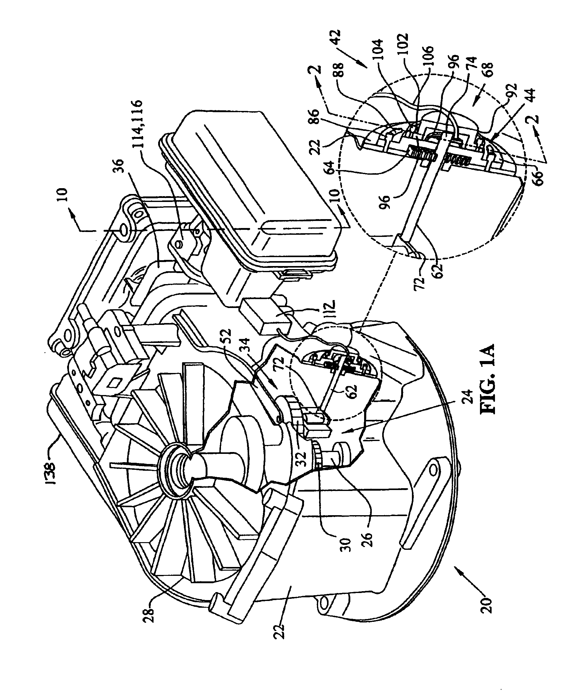
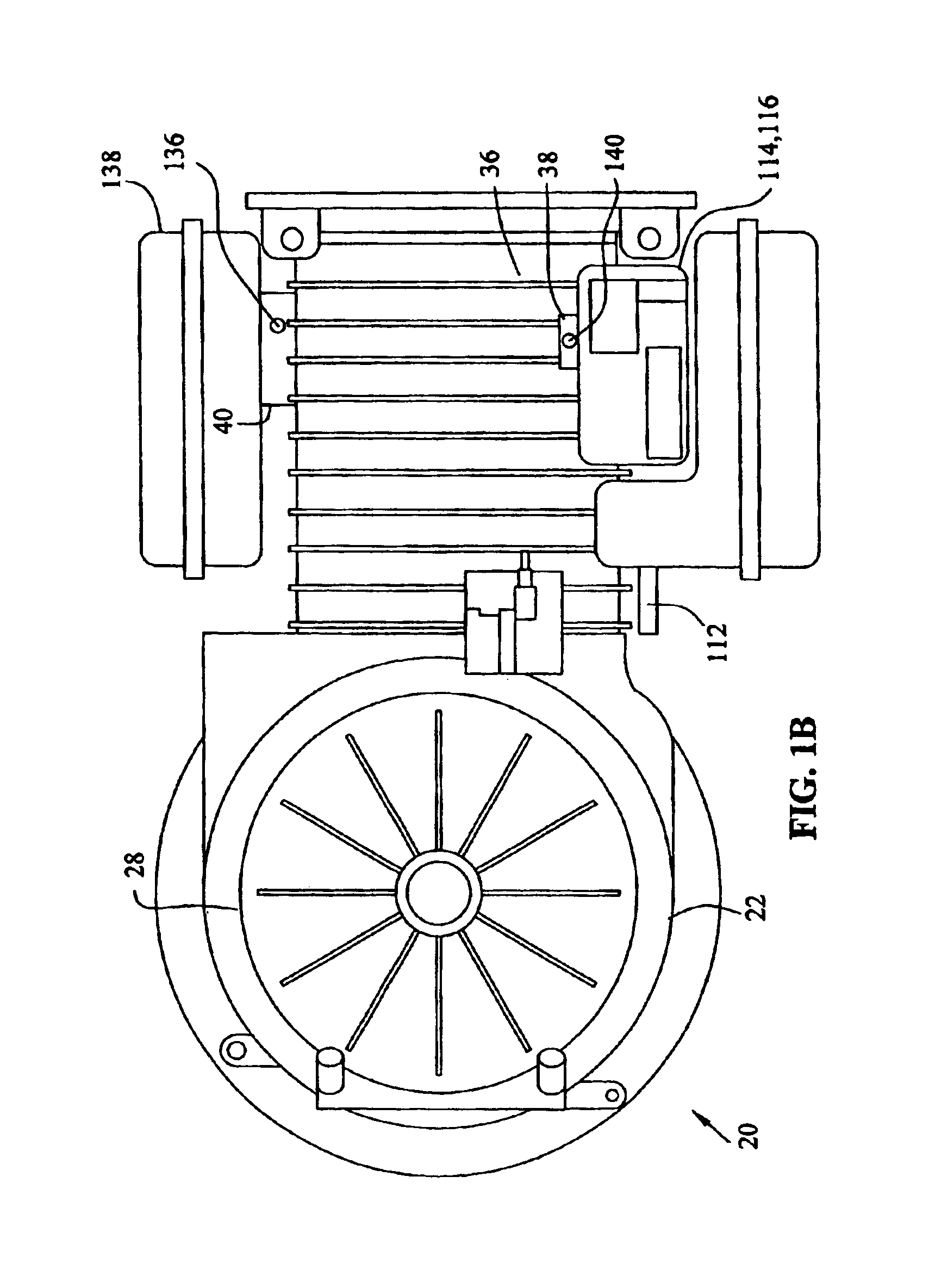
[0042]Referring to FIG. 1A, small internal combustion engine 20 is shown, including engine housing 22 with crankcase 24, crankshaft 26 located internal to and supported by housing 22, and flywheel 28 mounted to an end of crankshaft 26 extending outside of housing 22. Crankshaft 26 is coupled to a piston (not shown) via a connecting rod (not shown), and further drives a valve train for actuating intake and exhaust valves within engine housing 22. The drive train of engine 20 may be of the overhead valve (OHV), overhead cam (OHC) L-head / side valve type, or another drive train type known in the art. Crankshaft gear 30, or another suitable drive mechanism, is mounted on crankshaft 26 for driving governor gear 32 of flyweight governor assembly 34. Flyweight governor assembly 34 may be located inside crankcase 24, and may be supported by housing 22. Referring to FIG. 1B, cylinder head 36 is supported by housing 22 and is connected to intake 38 and exhaust 40.

[0043]Referring again to FIG. ...


PUM


Abstract

An engine control system for maintaining the operator-commanded speed setting of an internal combustion engine over a range of engine loads and for easy starting and improved efficiency over a range of ambient and engine operating temperatures. The engine control system includes a governor assembly driven by the engine, the governor assembly supplying an output to a sensor assembly through a mechanical coupling member operator. The sensor assembly provides an engine speed control signal which corresponds to operator commanded engine speed and actual engine speed. The engine speed control signal is provided to a throttle actuator to control actual engine speed is controlled to correspond with the operator-commanded engine speed regardless of loads imposed on the engine.

Description

[0001]This application claims the benefit of U.S. Provisional Application No. 60 / 416,859 filed Oct. 8, 2002 and claims the benefit of U.S. Provisional Application No. 60 / 448,263 filed Feb. 17, 2003.BACKGROUND OF THE INVENTION[0002]1. Field of the Invention[0003]The present invention relates to engine control for internal combustion engines and, more particularly, for small internal combustion engines of the type which are used in a variety of applications, such as walk-behind lawnmowers, lawn and garden implements, generators, or in small utility vehicles such as riding lawnmowers, lawn tractors, and the like.[0004]2. Description of the Related Art[0005]Small internal combustion engines generally include an operator-selected command speed setting, for example, a throttle control for utility vehicles or a normal / idle switch for generators. However, driving a variable load may reduce or increase the engine speed from the commanded setting. For example, in a lawnmower powered by an int...

Claims


Application Information

Patent Timeline
Patent Type & Authority Patents(United States)
IPC IPC(8): F02D31/00F02D41/06F02D41/16F02D11/10F02D9/02
CPCF02D11/105F02D31/00F02D31/008F02D35/025F02D41/062F02D41/16F02D41/1446F02D41/187F02D2009/0216F02D2200/0404F02D2200/0414
Inventor RADO, GORDON E.
Owner TECUMSEH POWER
Why Eureka
Try Eureka