Electric toothbrush

a toothbrush and electric technology, applied in the field of electric toothbrushes, can solve the problems of increasing the difficulty of cleaning the inability to achieve true additional cleaning benefits, and the inability to achieve motorized motions in a commercially feasible manner, so as to facilitate the access to facilitate the use of the back of the user's mouth, and avoid vibration. the effect of discomfor

Inactive Publication Date: 2005-08-23
CHURCH & DWIGHT CO INC
View PDF198 Cites 60 Cited by
  • Summary
  • Abstract
  • Description
  • Claims
  • Application Information

AI Technical Summary

Benefits of technology

[0034]One advantage of the present invention is the provision of an electric toothbrush with a brush head with a traditional larger brush head shape to permit the user to brush teeth in an up and down fashion.
[0035]Another advantage of the present invention is the provision of an electric toothbrush which is inexpensive and easy to manufacture.
[0036]Another advantage of the present invention is the provision of an electric toothbrush with an angled shaft to permit easier access to the back of the user's mouth.
[0037]Still another advantage of the present invention is the provision of an electric toothbrush with a static portion and a circular or moving portion that rotates, swivels, oscillates or reciprocates.
[0038]Yet another advantage of the present invention is the provision of a circular portion that rotates or reciprocates or swivels or oscillates which is positioned at the end of the brush head to facilitate easier access to the back of the user's mouth.
[0039]Yet still another advantage of the present invention is the provision of an electric toothbrush with a switch which allows momentary operation or continuous operation of the toothbrush.

Problems solved by technology

However, an examination of the available technology shows a tendency toward increasingly complex, expensive, and non-commercially feasible methods of achieving motorized motions in the bristles and heads of toothbrushes to aid in more effectively cleaning one's teeth.
The lower end of the market has become the province of very simple motorized toothbrushes that only vibrate through the use of an offset weight attached to the motor shaft, and which provide very little true additional cleaning benefit with their use, since no vigorous motion is transmitted to the cleaning surface of the brush.
The vibrations are also very uncomfortable to the hand and act as a disincentive to brush one's teeth for an adequate time.

Method used


Image

  • Electric toothbrush
  • Electric toothbrush
  • Electric toothbrush

Examples


first embodiment

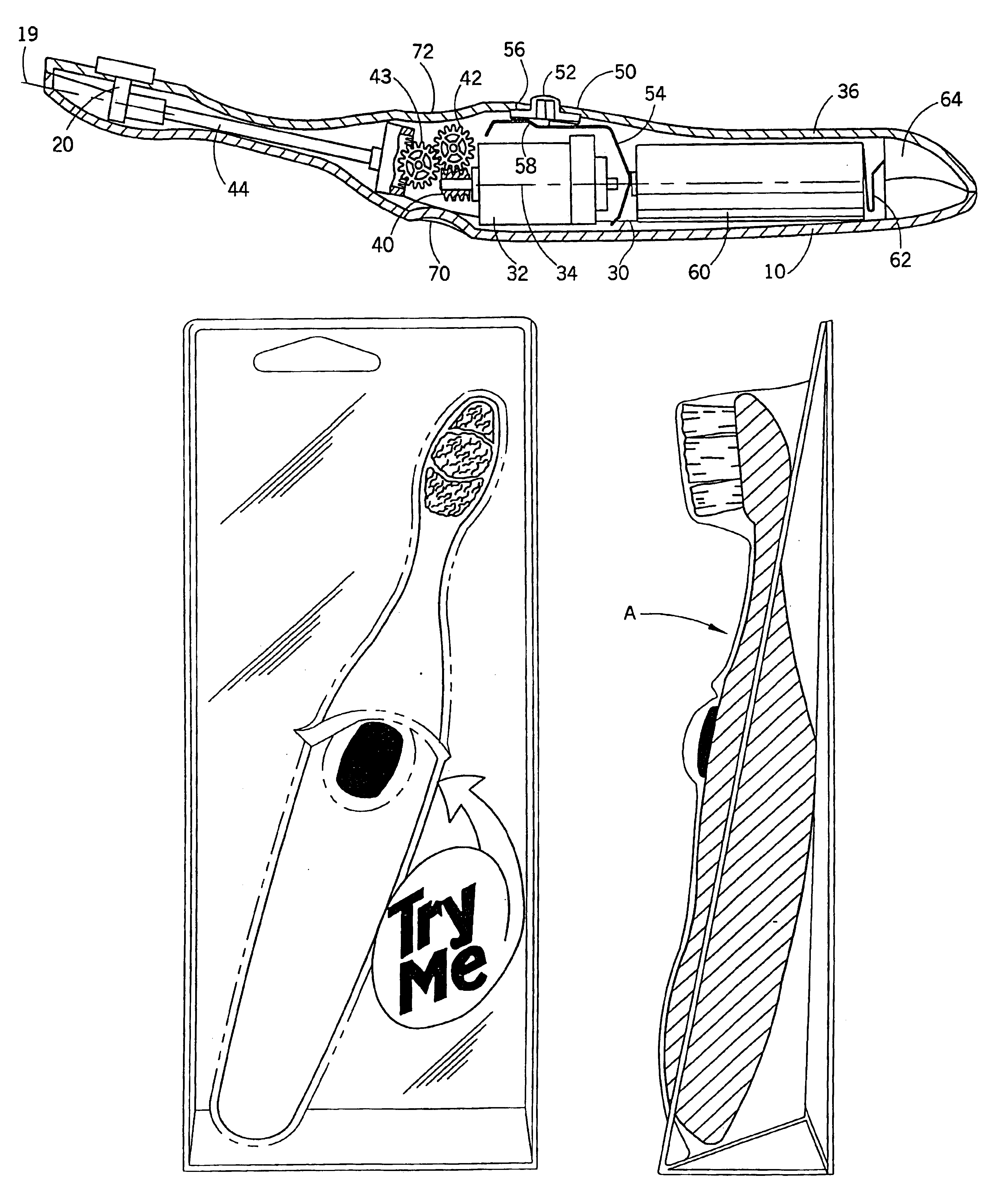
[0090]The elongated body portion 150 of the third preferred embodiment also includes a hollow portion 196 which houses a motor 200. The hollow portion 196 is formed between the upper housing 192 and the lower housing 194. The motor 200 provides power to the moving portion 164 to rotate or oscillate or reciprocate. Power is provided to the motor by battery as shown and described for the

[0091]A switch (not shown) can be provided which is similar to switch 130 shown in FIGS. 9 and 11 and which functions as described for the first and second preferred embodiments.

third embodiment

[0092]The third embodiment further includes a first gear 202 which is operatively connected to and powered by the motor 200. The first gear 202 rotates about the longitudinal axis 172 of the elongated body portion 150. A second gear 206 is operatively connected to the first gear 202. The second gear 206 is approximately normal to the first gear 202. The second gear 206 rotates about an axis approximately normal to the longitudinal axis 172. Teeth 208 of the first gear 202 mesh with teeth 210 of the second gear 206, thus causing second gear 206 to rotate when first gear 202 rotates.

[0093]A first swivel arm 220 is pivotably connected to the second gear 206 via a pin 222 or other fastening device. The pin 222 or other fastening device is mounted on the second gear 206 at a point offset from an axis of rotation of the second gear. Therefore, the first swivel arm 220 is pivotably connected to the second gear 206 at a point offset from an axis of rotation of the second gear. A second swiv...

fourth embodiment

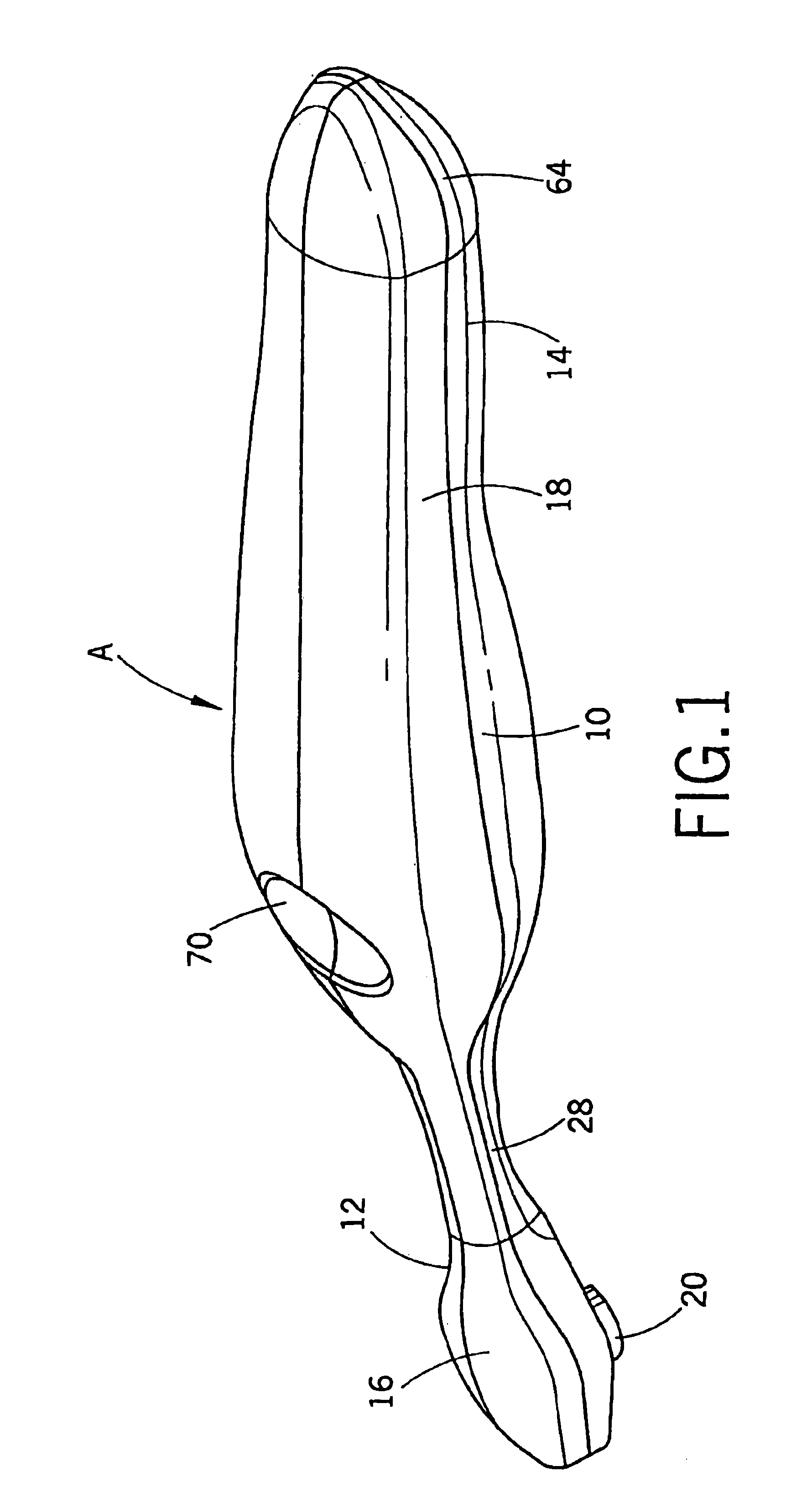
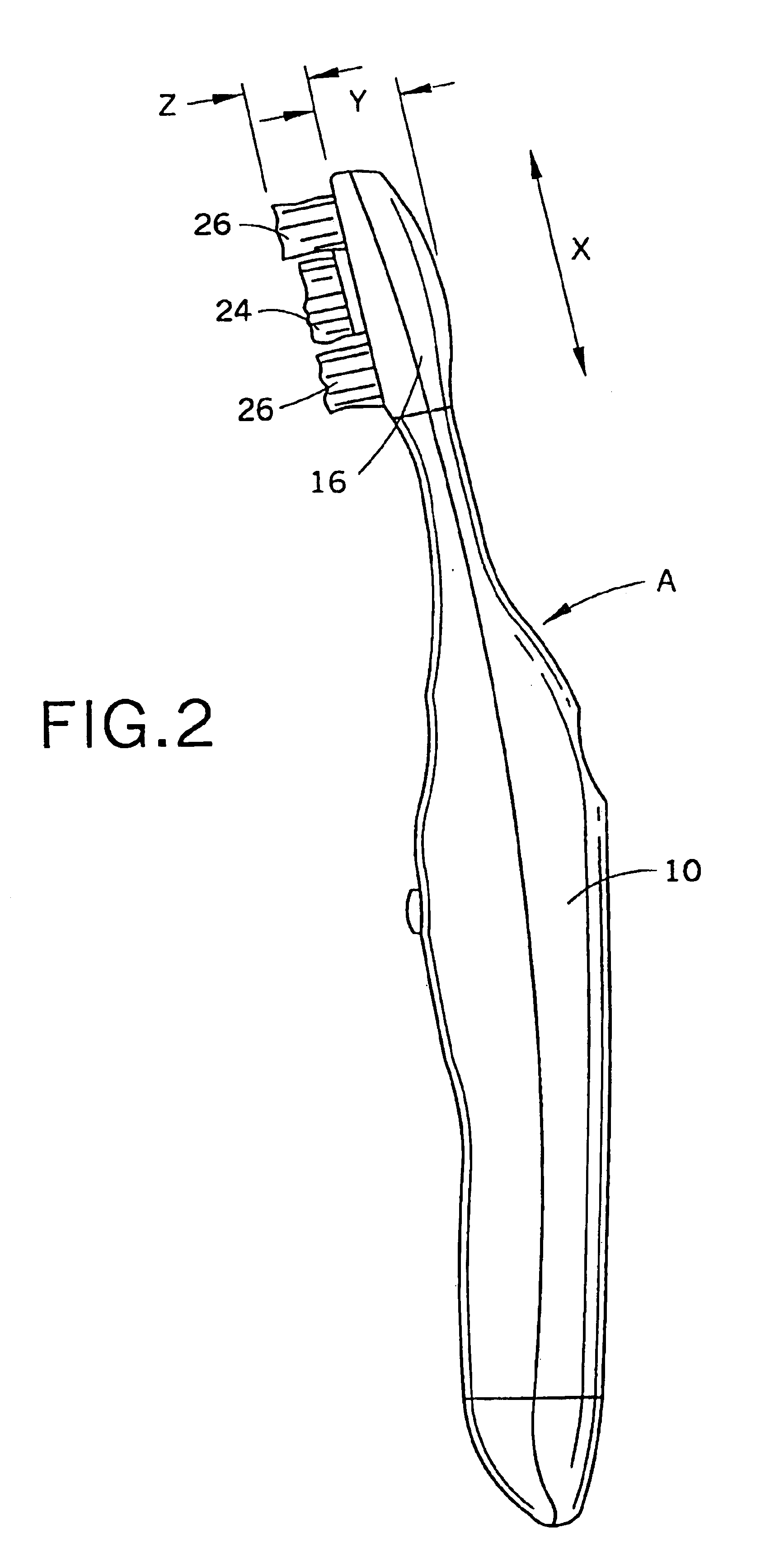
[0104]the present invention is shown in FIGS. 13 and 14. The head of the electric toothbrush is illustrated. The remaining portion of the brush, including the handle, motor, etc. is the same as described for any of the previously described embodiments. As shown in FIG. 13, a head 316 includes a longitudinal axis 319, a circular or moving portion or brush head 320 and a static portion or brush head 322. The head 316 is located adjacent a first end 328 of an elongated body portion. The static portion 322 is located on opposite sides of the moving portion 320. The moving portion 320 is located at the center of the brush head 316. The circular portion 320 rotates, swivels, oscillates or reciprocates about an axis approximately normal to the longitudinal axis 319 of the brush head. The circular portion 320 may rotate 360 degrees or partially rotate or oscillate or reciprocate in a back and forth manner.

[0105]The moving portion 320 includes bristles 324 and massaging tips 325. The static ...


PUM

PropertyMeasurementUnit
lengthaaaaaaaaaa
lengthaaaaaaaaaa
lengthaaaaaaaaaa

Abstract

An electric toothbrush comprises a body portion and a head including a motor, a moving portion, a handle, and a gear arrangement between the moving portion and the motor. The moving portion rotates, oscillates and/or reciprocates about an axis normal to a longitudinal axis of the head. The moving portion can include stiff bristles and massaging tips and the static portion can include soft bristles and massaging tips. The body portion houses the motor. A switch is operatively connected to the motor to provide momentary or continuous operation of the toothbrush. In one embodiment the gear arrangement includes a shaft, a worm gear and a pair of step gears. In another embodiment the gear arrangement includes a plurality of gears and at least one swivel arm for drive the moving portion in a rotating, oscillating or reciprocating manner.

Description

[0001]This application is a continuation of application Ser. No. 09 / 710,616, filed on Nov. 9, 2000, now U.S. Pat. No. 6,371,294, which is a continuation-in-part of application Ser. No. 09 / 382,745, filed on Aug. 25, 1999, now, U.S. Pat. No. 6,178,579, which is a continuation-in-part of application Ser. No. 09 / 236,794, filed Jan. 25, 1999, now U.S. Pat. No. 6,189,693, which is a continuation-in-part of application Ser. No. 09 / 163,621, filed on Sep. 30, 1998, which issued as U.S. Pat. No. 6,000,083 on Dec. 14, 1999.BACKGROUND OF THE INVENTION[0002]The present invention relates generally to electric toothbrushes. More particularly, it relates to an improved battery powered toothbrush.[0003]The benefits of brushing one's teeth using motorized toothbrushes are well known, and motorized movement in toothbrushes has been the subject of much recent innovation and design activity. Also, the commercial market has seen the introduction, over the last several years, of many different types of mo...

Claims


Application Information

Patent Timeline
Patent Type & Authority Patents(United States)
IPC IPC(8): A61C17/22A61C17/26A61C17/34A61C17/16A61C17/00A61C19/02B29C65/02
CPCA61C17/22A61C17/221A61C17/26A61C17/34A61C17/3436A61C17/349A61C19/02B29C65/02B29C66/54B29L2031/425A61C2204/002
Inventor BLAUSTEIN, LAWRENCE A.NOTTINGHAM, JOHN R.OSHER, JOHNSPIRK, JOHN W.GALL, DOUGLAS A.
Owner CHURCH & DWIGHT CO INC
Why Eureka
Try Eureka