Cup-shaped receptacle and lid

Inactive Publication Date: 2005-08-23
SEDA SPA
View PDF13 Cites 36 Cited by
  • Summary
  • Abstract
  • Description
  • Claims
  • Application Information

AI Technical Summary

Benefits of technology

[0026]The centring and guide projection, in this case, ought to be continued downwardly by an inward stepped portion of the outer leg wall dimensioned for a press-fit co-action with the receptacle wall. The inwardly stepped portion should have a cone

Problems solved by technology

Due to the comparatively short outer surface and the large radial dimension of the U-web of the lid recess, the clamping groove tilts inwards during the clip-on movement; this hinders the bead to smoothly move over the whole circumferential length past the constriction.
This clip on action is troublesome, time-consuming and increases the

Method used


Image

  • Cup-shaped receptacle and lid
  • Cup-shaped receptacle and lid
  • Cup-shaped receptacle and lid

Examples


Embodiment Construction

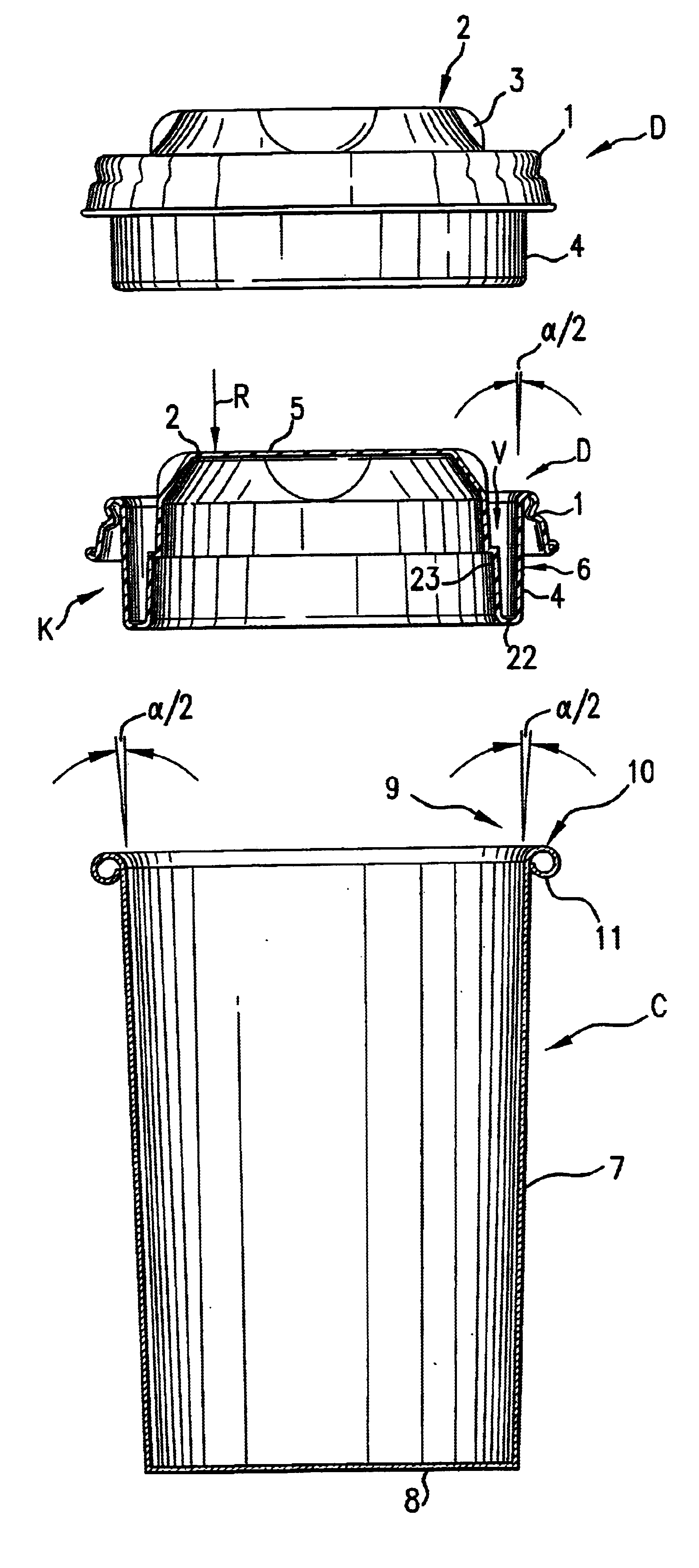
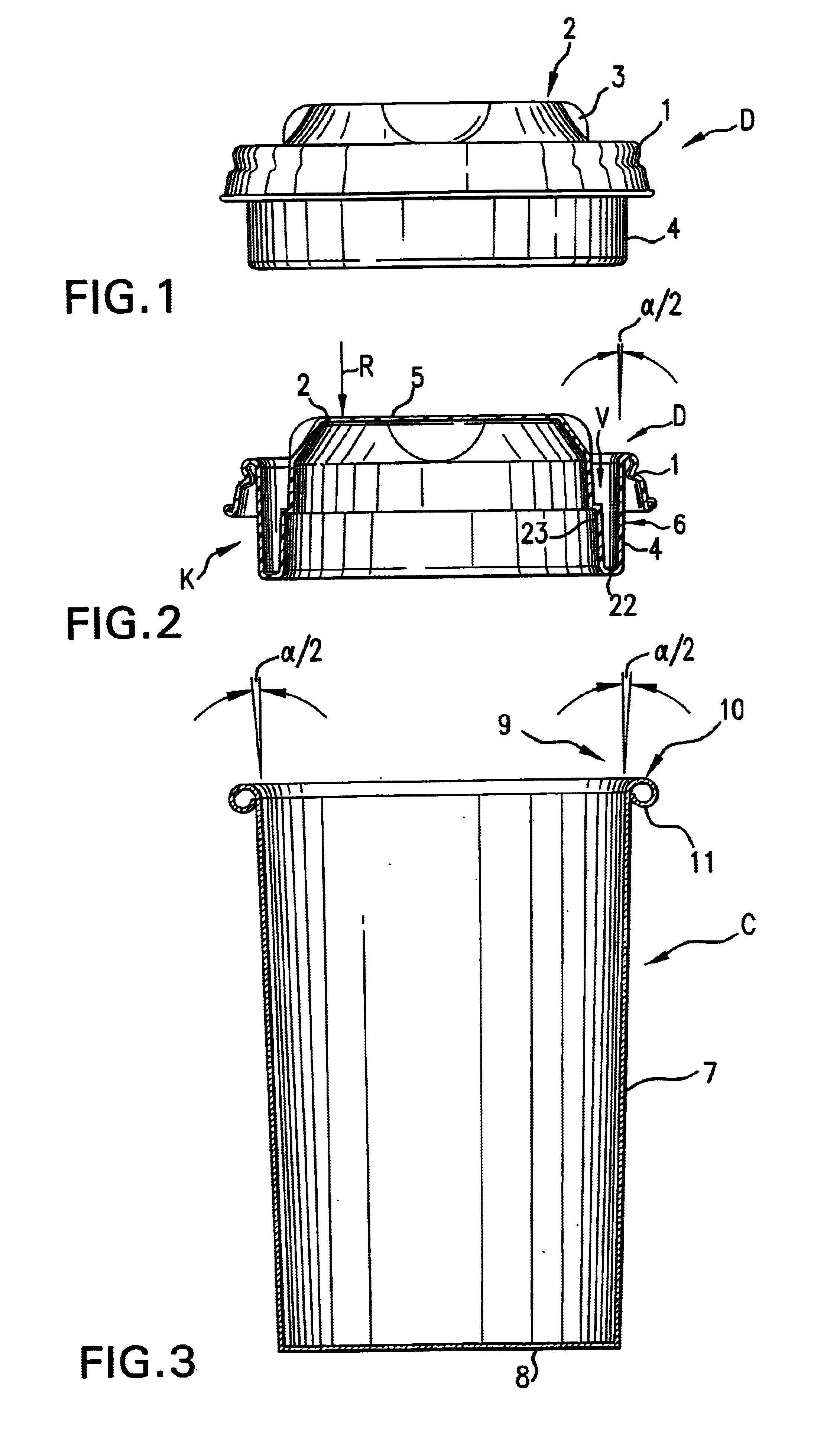
[0046]A lid D, which is intended to be used for a cup-shaped receptacle C consisting of paper or paperboard or plastic material is e.g. drawn from elastic plastic foil material and has a wall thickness of e.g. 0.3 to 0.5 mm (FIG. 1). The lid is adapted to be clipped on an opening area 9 of the receptacle C such that said receptacle C is closed in a leakage-free manner and such that the lid D will not come off, not even if the full receptacle C falls over. The lid D (FIG. 1) is provided with a peripheral, circumferentially continuous clamping groove 1, above the plane of which a dome 2 vaults on the inner side of the clamping groove 1. The dome 2 is separated from the clamping groove 1 by a circumferential substantially uniform lid recess V and is provided with an essentially planar dome top wall 5 and several circumferentially distributed depressions 3. Relative to the clamping groove 1, an outer leg wall 4 of a lid recess V (FIG. 2) extends markedly downwards beyond the plane of th...


PUM

PropertyMeasurementUnit
Fractionaaaaaaaaaa
Fractionaaaaaaaaaa
Angleaaaaaaaaaa

Abstract

A cup-shaped receptacle has an outer bead in its opening area for clipping on a plastic lid, which has a circumferentially continuous clamping groove for receiving the bead. The clamping groove is continued outwards by an elastically deformable constriction, and inwards by an outer wall of a circumferentially continuous, U-shaped lid recess, whose U-web of is situated below the height position of the constriction and whose inner leg wall forms a part of a dome wall of a dome which extends upwardly beyond the height position. The lid recess extends downwards beyond the height position and has an outer diameter at its outer surface which is adapted to the inner diameter of the receptacle wall such that the lid recess functions at least as a centring and guide projection for the lid-clip-on action, which projection slidingly co-operates with the receptacle wall already at least while the bead passes the constriction.

Description

FIELD OF THE INVENTION[0001]The present invention relates to a cup-shaped receptacle and to a lid for such a receptacle.BACKGROUND OF THE INVENTION[0002]Of the clip-on plastic lid on the cup-shaped receptacle in U.S. Pat. No. 5,253,781 A, the outer surface of the outer leg wall of the lid recess extends downwards just slightly beyond the height position of the constriction. The cone angle and the outer diameter of the outer surface are matched with the cone angle and the inner diameter of the receptacle wall such that outer surface does not get in significant contact with the receptacle wall even when the bead of the receptacle, which is implemented as a curled rim, fully is seated on the clamping groove. Due to the comparatively short outer surface and the large radial dimension of the U-web of the lid recess, the clamping groove tilts inwards during the clip-on movement; this hinders the bead to smoothly move over the whole circumferential length past the constriction. It is neces...

Claims


Application Information

Patent Timeline
IPC IPC(8): B65D43/02
CPCB65D43/0212B65D2203/00B65D2231/02B65D2543/00027B65D2543/00092B65D2543/00296B65D2543/00351B65D2543/00509B65D2543/00537B65D2543/00555B65D2543/00638B65D2543/00685B65D2543/00731B65D2543/00796B65D2543/00805
Inventor D'AMATO, GIANFRANCO
Owner SEDA SPA
Why Eureka
Try Eureka