Pivoting joint for pivotally joining a brake head to a brake beam

a technology of pivotal joint and brake head, which is applied in the direction of couplings, rod connections, manufacturing tools, etc., can solve the problems of reducing the life of the brake shoe. , to achieve the effect of extending the life of pins, levers, and pocket guides

Inactive Publication Date: 2005-08-23
A STUCKI CO
View PDF21 Cites 6 Cited by
  • Summary
  • Abstract
  • Description
  • Claims
  • Application Information

AI Technical Summary

Benefits of technology

[0019]It is also a main object of the present invention to provide a pivoting joint for pivotally joining a brake head to a brake beam, which allows the brake head to modify its radial and lateral direction with a controlled degree of rotation with respect to the brake beam by self-adjusting with respect to the wheel, thus transferring optimum braking forces to the wheels by preventing the buckling of its different elements, such as the end extensions on the truck guides and the lever on the strut, aiming to correct common brake problems in low braking applications and hand brake applications, for all types of brake rigging mechanisms (BMS & TMS).
[0020]It is a further object of the present invention to provide a pivoting joint for pivotally joining a brake head to a brake beam, by which a uniform force distribution is achieved along the brake shoe, thus allowing the brake shoe material of the brake head to adapt to the wheel thread as the material of the brake shoe is worn.
[0021]It is still another object of the present invention to provide a pivoting joint for pivotally joining a brake head to a brake beam, by which all the useful material of the brake shoe is totally used, thus avoiding frequent changes of the brake shoe material.
[0022]It is still another object of the present invention to provide a pivoting joint for pivotally joining a brake head to a brake beam, by which an uniform and complete wear of all the brake shoe material is achieved.
[0023]It is another object of the present invention to provide a pivoting joint for pivotally joining a brake head to a brake beam that reduces the torsional forces induced by the levers at certain angles during operation, thus extending the life of pins, levers, pocket guides, and the beam itself, by avoiding the buckling of the elements, and allowing the rigging system to apply a uniform force to all wheels on the transportation apparatus, such as a truck.

Problems solved by technology

Furthermore, during the braking operation, due to existent fixed joints between the extensions of the brake beam and its truck guides, between the brake heads and the wheels during the braking operation, and between the brake head and the brake beam, there is a double restriction that somehow buckles the displacement of the beam in the truck guides as well as its self-alignment towards the wheel center, so that the forces applied through the brake head are not transmitted uniformly along the brake shoe, thus producing a non-uniform and incomplete wear of the useful material of the brake shoes, which is a waste of useful material that could be properly used, and therefore, it is necessary to frequently change the brake shoe material which is a waste of time and money.
In many occasions this uneven taper wear leaves the shoe material at the bottom of the shoes in as-new condition, while the top has already reached the condemnable limits, thus producing a material waste of approximately 50%.
In extreme cases, the material of the brake shoe is so worn at some points that the metal of the brake shoe carrier comes in direct contact with the corresponding bogie wheel, damaging the brake shoe carrier as well as the wheel.
It is also a common problem that, as the cars run through their cycle life, the components of its brake rigging system gradually wear out, aggravating the conditions of the beam hanging and buckling as referred above, thus further reducing the useful life of the brake shoes as the car ages.

Method used


Image

  • Pivoting joint for pivotally joining a brake head to a brake beam
  • Pivoting joint for pivotally joining a brake head to a brake beam
  • Pivoting joint for pivotally joining a brake head to a brake beam

Examples


Embodiment Construction

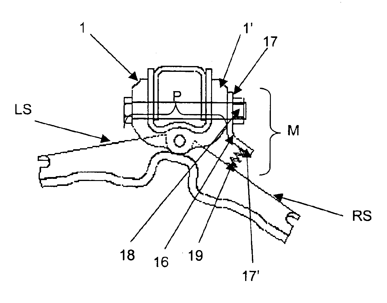
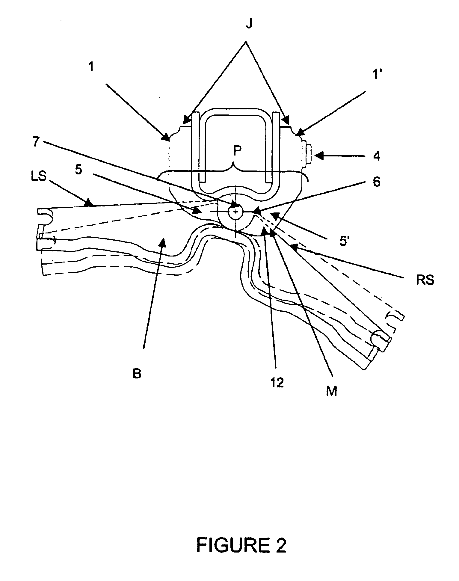
[0031]As shown in FIGS. 1-5, the present invention can be used in various transportation apparatus which employ brake systems, such as the brake system described in co-pending U.S. application Ser. No. 09 / 668,483, filed Sep. 25, 2000, which is incorporated herein by reference. Although described herein with reference to an example embodiment for a railroad car, the present invention may be implemented in various transportation apparatus not limited to railroad cars, such as trucks and other vehicles using brake systems.

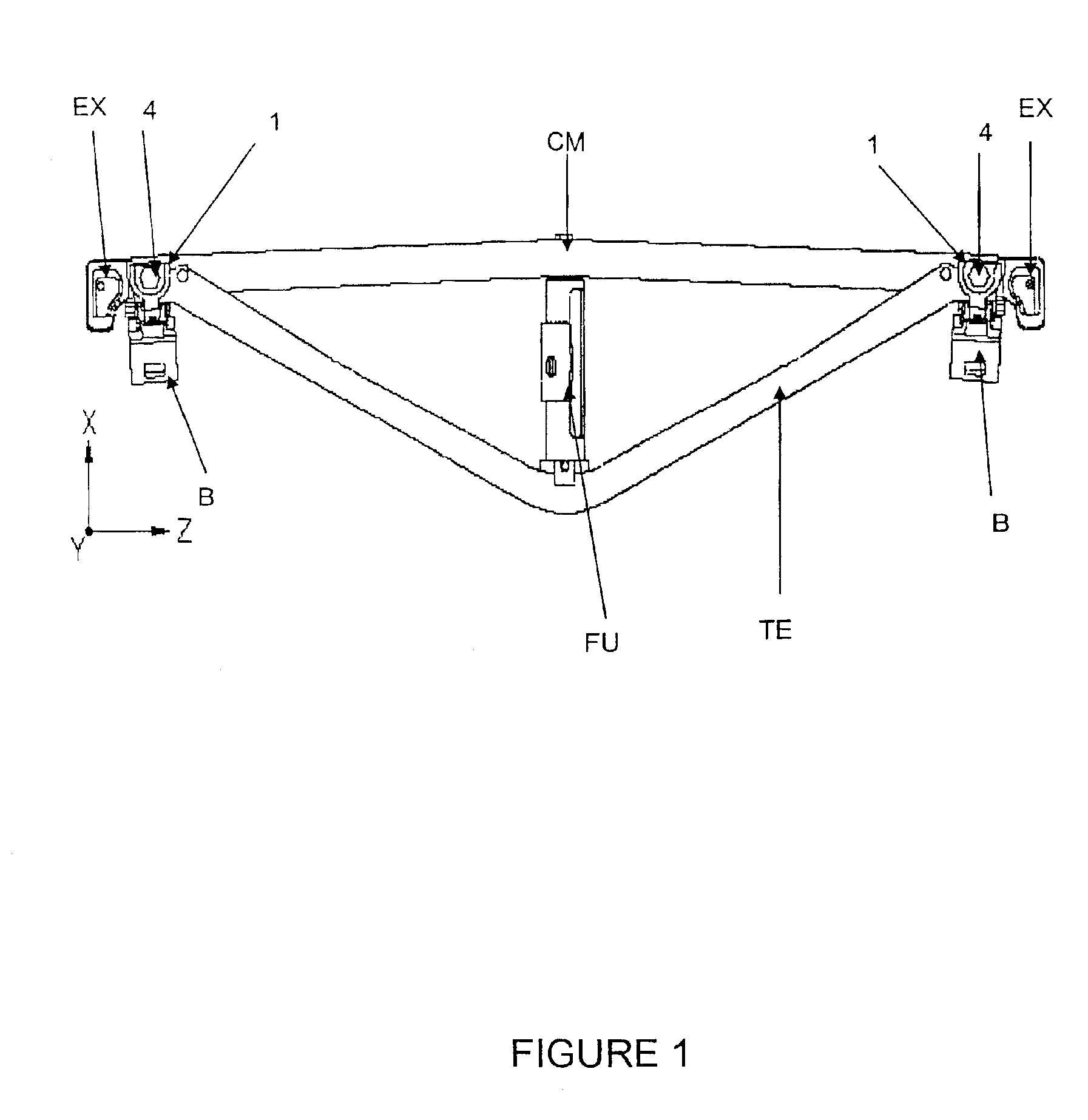
[0032]Referring to FIG. 1, a typical brake beam comprises: a compression member “CM”, a generally “V” shaped tension member “TE” having its ends coupled to the ends of the compression member “CM”, each end including a first and a second longitudinal side and a first and a second end, a brake head “B” linked to each end of the compression and / or tension member, two end extensions “EX” or hanging means by which the brake beam is coupled to the bogie of a railway car, an...


PUM


Abstract

A pivoting joint for pivotally joining a brake head to a brake beam of a railway car allows the brake head to modify its radial and lateral direction with a controlled degree of rotation with respect to a bogie wheel, allowing the brake shoe to adapt to the wheel contour, and achieving an adequate force distribution along the brake shoe, and thus optimizing the utilization of the brake shoe material.

Description

CROSS-REFERENCE TO RELATED APPLICATIONS[0001]This invention is related to U.S. application Ser. No. 09 / 668,483, filed Sep. 25, 2000, now U.S. Pat. No. 6,551,003 B1, issued Apr. 22, 2003, which is incorporated herein by reference.BACKGROUND OF THE INVENTION[0002]1. Field of the Invention[0003]The present invention is related to brake head assemblies for using in brake beams of railway cars, and more particularly to a pivoting joint for pivotally joining a brake head to a brake beam of a railway car by which an adequate force distribution along the brake shoe and an adequate contact between the brake shoes and the railway car bogie wheels are achieved.[0004]2. Description of the Related Art[0005]Most railroad freight cars and other transportation apparatus use a mechanism called brake rigging, classified generally as either a Body Mounted System (BMS) with an actuator on the car platform; a Truck Mounted System Direct Acting (TMS-DA) with an actuator on the beam; or a Truck Mounted Sy...

Claims


Application Information

Patent Timeline
Patent Type & Authority Patents(United States)
IPC IPC(8): B61H13/36B61H13/00
CPCB61H13/36Y10T403/32106Y10T403/32614Y10T403/535
Inventor DE LA FUENTE-FARIAS, JORGE ALBERTO
Owner A STUCKI CO
Why Eureka
Try Eureka