Display system including functional layers and electronic device having same

Inactive Publication Date: 2005-08-23
BOE TECH GRP CO LTD
View PDF20 Cites 30 Cited by
  • Summary
  • Abstract
  • Description
  • Claims
  • Application Information

AI Technical Summary

Benefits of technology

[0011]In order to make the light-emitting element 910 emit light with stability, it is needed to minimize change in t

Problems solved by technology

Therefore, images cannot be normally displayed due to faults in

Method used


Image

  • Display system including functional layers and electronic device having same
  • Display system including functional layers and electronic device having same
  • Display system including functional layers and electronic device having same

Examples


Example

[0049]A first embodiment of the present invention will now be described with reference to the accompanying drawings. It should be understood that this is merely one of the embodiment of the present invention, and the present invention is not limited to this embodiment. Within the scope of the present invention, various changes may be performed. In the following drawings, in order to show each layer and member in the drawings on a recognizable scale, different scales are used for showing the layers and members.

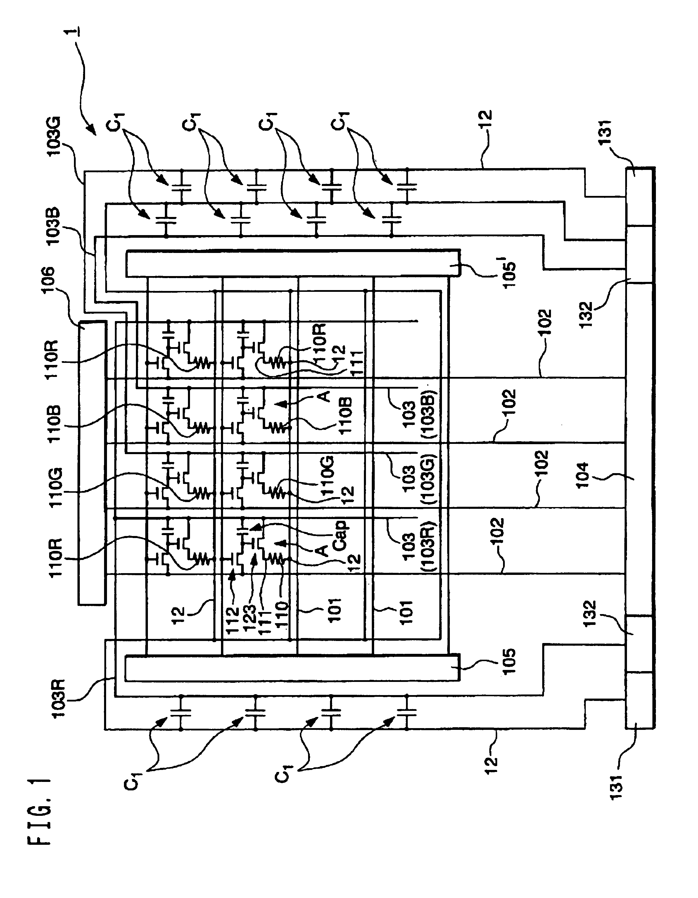
[0050]FIG. 1 is a schematic plan view showing a wiring structure of a display system of this embodiment. The display system 1 shown in FIG. 1 is an active matrix-type organic EL display system equipped with a thin-film transistor functioning as a switching element. As shown in FIG. 1, the display system 1 of this embodiment includes a plurality of scanning lines 101, a plurality of signal lines 102 extending in the direction that intersects the scanning lines 101, and a plurali...

Example

[0142]A second embodiment of the present invention will now be described with reference to the accompanying drawings. This is one of the embodiments of the present invention, and the present invention is not limited to this embodiment. Within the scope of the present invention, various changes may be performed. In the following drawings, in order to show each layer and member in the drawings on a recognizable scale, different scales are used for showing the layers and members.

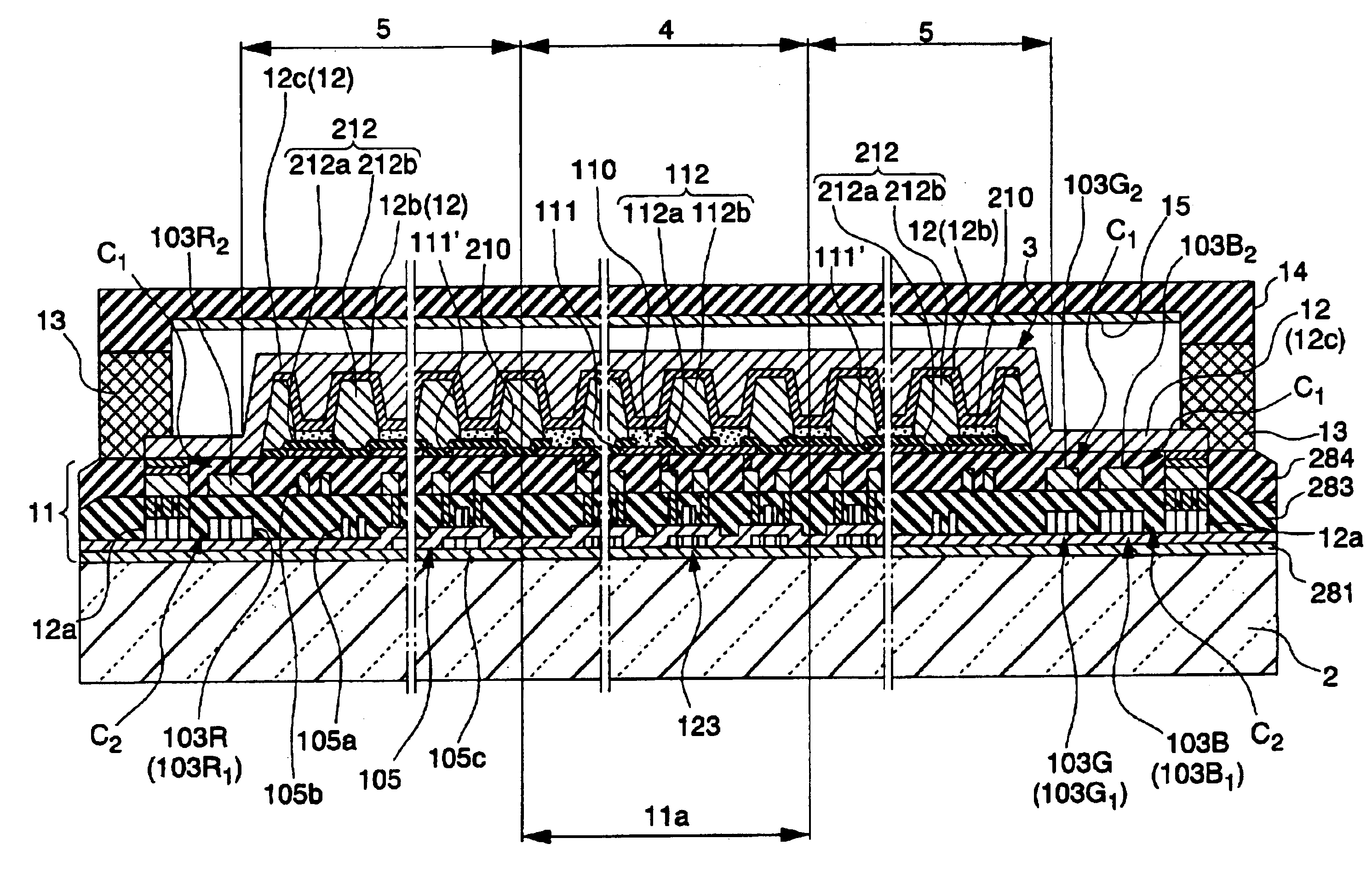
[0143]FIGS. 10 and 11 show an example of a display system 101 of this embodiment. FIG. 10 is a schematic plan view showing the display system 101 of this embodiment, and FIG. 11 is a sectional view taken along the line A—A′ of FIG. 10. Among components shown in FIGS. 10 and 11, the same components as those shown in FIGS. 2 and 3 illustrated above have the same reference numerals in order to omit or simplify the description.

[0144]As shown in FIG. 10, the display system 101 of this embodiment includes a substrate...


PUM


Abstract

The invention provides a display system for displaying images and an electronic device equipped with the display system. The display system can include a first electrode region in which first electrodes connected to switching elements are arranged on a substrate in a matrix, and light-emitting power-supply lines that are arranged around the first electrode region and are connected to the first electrodes. Functinal layers are formed over the first electrodes, and a second electrode is formed at least over the functional layers. Each light-emitting power-supply line and the second electrode have a first capacitor therebetween.

Description

BACKGROUND OF THE INVENTION[0001]1. Field of Invention[0002]The present invention relates to a display system including an organic electroluminescent material and relates to an electronic device.[0003]2. Description of Related Art[0004]Recently, color display systems having a luminescent layer including a luminescent material, such as an organic fluorescent material being disposed between a pixel electrode (anode) and a cathode have been developed. Particularly, an organic EL display system including a luminescent material, such as an organic electroluminescent (organic EL) material has been developed.[0005]A conventional display system (organic EL display system) will now be described with reference to the accompanying drawing. FIG. 13 shows a wiring structure of the conventional display system. The conventional display system has a plurality of scanning lines 901, a plurality of signal lines 902 extending in the direction that intersects the scanning lines 901, and a plurality of ...

Claims


Application Information

Patent Timeline
IPC IPC(8): G09G3/32H01L27/32H01L27/28G09G3/00H05B33/00
CPCG09G3/3233H01L27/3265H01L27/3276G09G3/006G09G2300/0426G09G2300/0842G09G2320/02G09G2320/0223G09G2330/025H01L27/3211H01L27/3223H10K59/88H10K59/35H10K59/1216H10K59/131H05B33/00
Inventor NAKANISHI, HAYATO
Owner BOE TECH GRP CO LTD
Why Eureka
Try Eureka