Electrical circuit tracing and identifying apparatus and method

Inactive Publication Date: 2005-08-23
ZIRCON
View PDF18 Cites 31 Cited by
  • Summary
  • Abstract
  • Description
  • Claims
  • Application Information

AI Technical Summary

Benefits of technology

[0017]Embodiments of the present invention provide an improved electrical circuit tracing and identifying apparatus and method. Specifically, accor

Problems solved by technology

The non-target neighboring circuits 15 re-radiate the coupled modulated signal and thus may lead to false-positive indications.
Consequently, these devices may create extraneous current noise at multiples or harmonics of the power line frequency.
A receiver 100 might not be immune to this current noise from active loads and may erroneously determin

Method used


Image

  • Electrical circuit tracing and identifying apparatus and method
  • Electrical circuit tracing and identifying apparatus and method
  • Electrical circuit tracing and identifying apparatus and method

Examples


Embodiment Construction

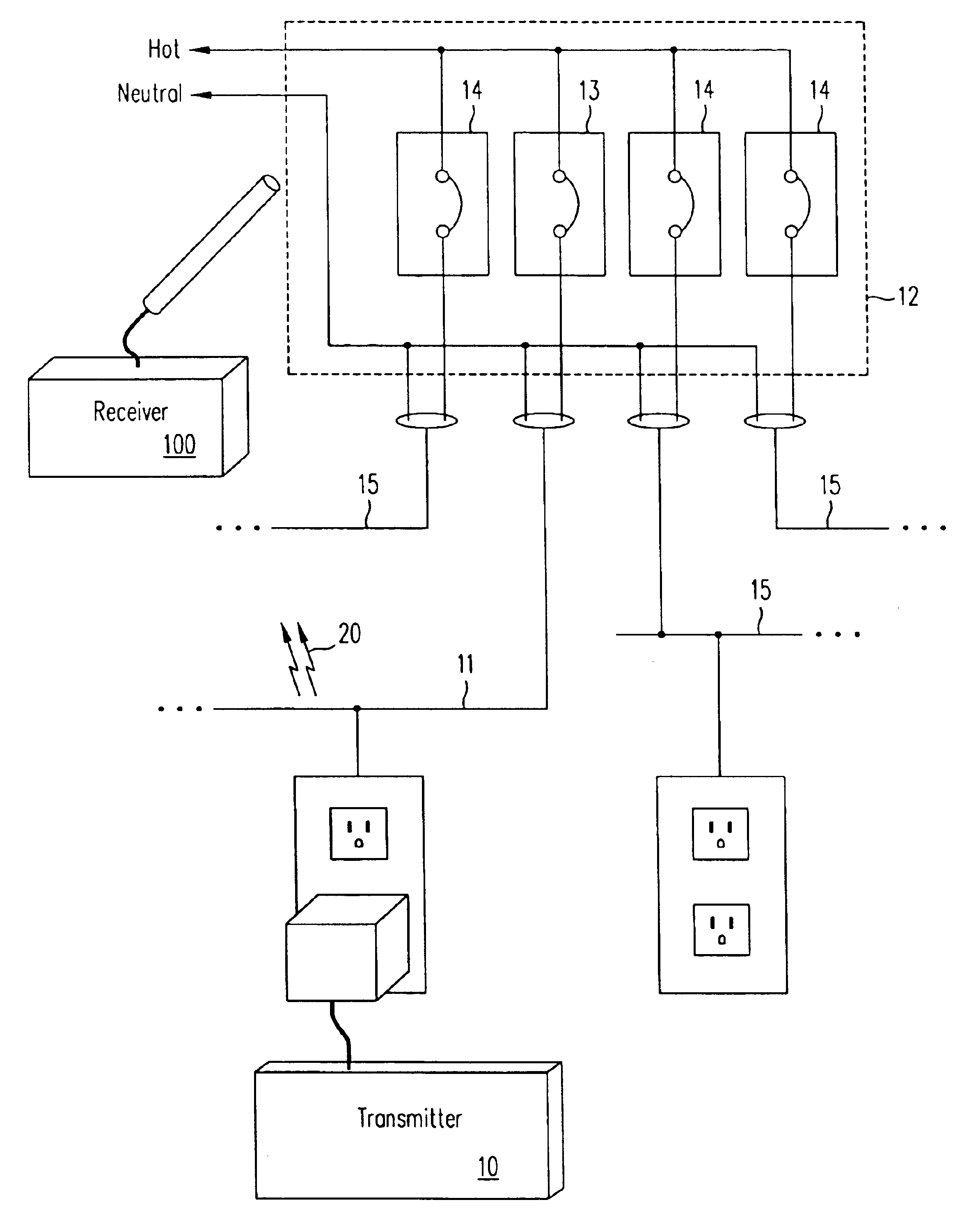
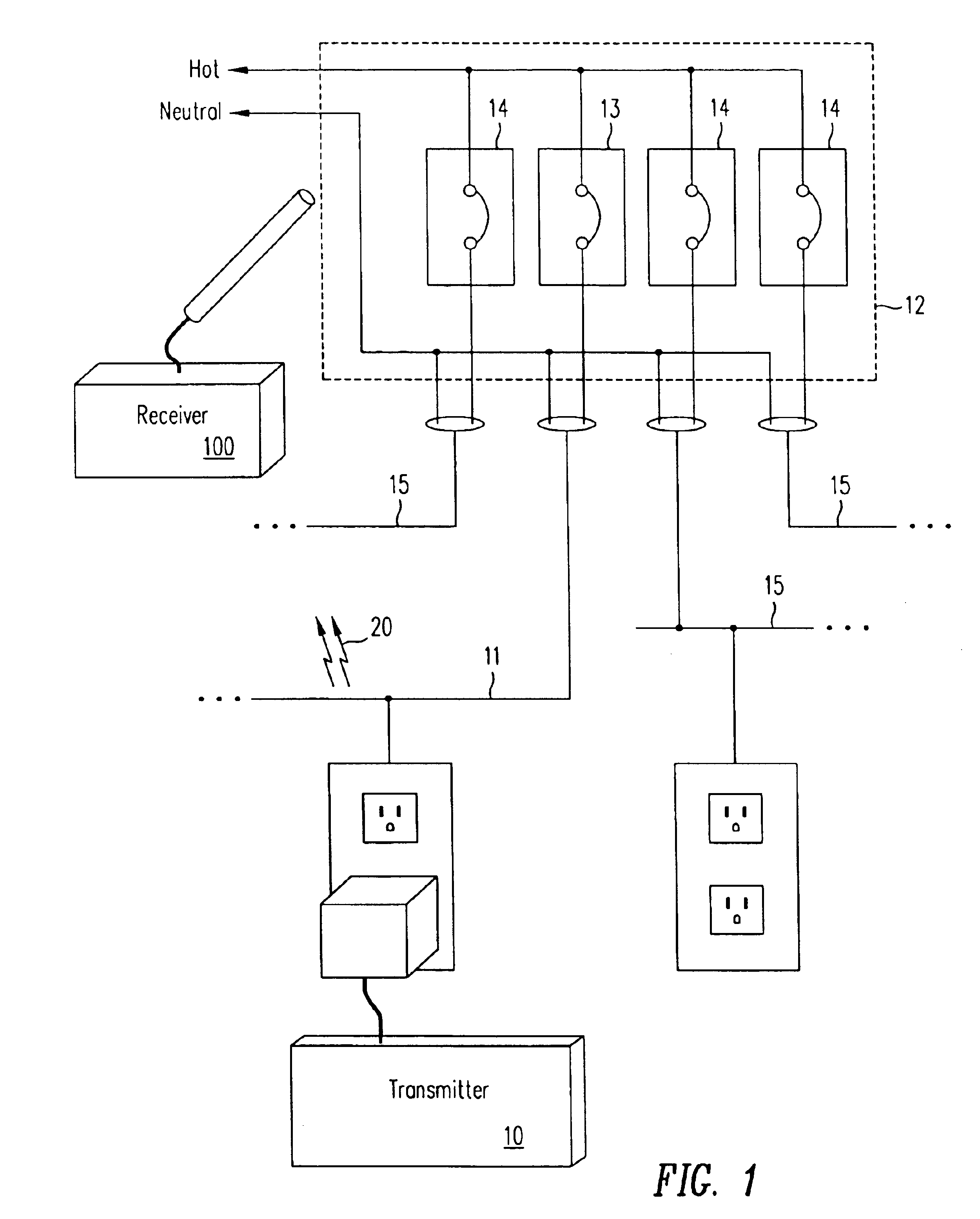
[0039]FIG. 1 illustrates how a transmitter 10 and a receiver 100 are used with a power distribution system. In some embodiments of the present invention, a transmitter 10 directly connects to a power distribution system through a wall outlet. In some embodiments, the transmitter 10 directly connects to the distribution wiring by, for example, jumper wires. The transmitter 10 then energizes a circuit 11 of the power distribution system. A receiver 100 detects electromagnetic radiation 20 induced by the transmitter 10. The receiver 100 senses the electromagnetic radiation 20 emanating from the energized wires of the circuit.

[0040]With proper modifications, some embodiments of the present invention may be used to identify circuit elements or to trace circuits on powered or un-powered lines. Powered lines may carry either alternating current (AC) or direct current (DC) at a low or high voltage.

[0041]For un-powered lines, power is disconnected from the circuit breaker box 12. The hot and...


PUM


Abstract

A transmitter that is electrically connected to a circuit and an associated receiver is used to identify an element of that circuit in the presence of other circuits. This may be used in AC or DC systems that are powered or not to identify or trace circuit elements such as lines, junctions, switches, fuses, or breakers. One version that identifies the circuit breaker of the circuit connected to the transmitter in a powered AC distribution system.

Description

BACKGROUND OF THE INVENTION[0001]1. Field of the Invention[0002]The present invention relates to electrical-test equipment used for tracing conductors and identifying electrical circuit elements.[0003]2. Discussion of Related Art[0004]Electrical work often requires identifying elements of a circuit or tracing a circuit behind a wall or other obstruction. For example, an electrician may wish to determine which circuit breaker is attached to a particular wall outlet so that repairs may be made. By identifying the proper circuit, the electrician can de-energize just a single circuit before performing the repairs. Typically, the electrician prefers not to shut down equipment attached to other circuits. Alternatively, the electrician may wish to trace a hidden wire along a wall to locate a convenient place to add another outlet.[0005]Some devices for locating and identifying electrical circuits use a transmitter and a receiver. A transmitter 10 induces a current signal on the circuit in ...

Claims


Application Information

Patent Timeline
IPC IPC(8): G01R29/08G01R19/145
CPCG01R29/085G01R19/145
Inventor MILLER, LARRYEHRENSBERGER, JR., PAUL DREW
Owner ZIRCON
Why Eureka
Try Eureka