Distributed load transmission line matching network

a technology of transmission line and distribution load, which is applied in the field of matching circuits, can solve the problems of less reliable deposition and removal processes, and achieve the effects of improving power delivered to the load, increasing the tuning range, and effectively minimizing the ac energy reflected from the load

Inactive Publication Date: 2005-08-23
APPLIED MATERIALS INC
View PDF15 Cites 0 Cited by
  • Summary
  • Abstract
  • Description
  • Claims
  • Application Information

AI Technical Summary

Benefits of technology

[0010]The previously identified needs as well as other needs are solved by embodiments of the present invention, which provide an apparatus and method for matching the impedance of a load to an ac power source. The apparatus includes a matching network coupled between an ac power source and a load. The matching network provides an increased tuning range for matching the impedance of the ac power source to the load. More specifically, an ac power source having a fixed source impedance can be matched to a load having a transient and variable impedance while the matching network effectively minimizes ac energy reflected from the load by improving power delivered to the load.
[0012]The apparatus and methods of use of the present invention are important to the manufacture of integrated circuit devices in which an RF source having a fixed impedance is coupled to a plasma load having a transient and variable impedance. The present invention is applicable to an ac energy delivery system in which ac energy delivered to a load needs to be maximized through the minimization of reflected energy. In integrated circuit manufacture plasma processes, both deposition and removal processes are less reliable when reflected energy is not minimized. Embodiments of the invention can be used to minimize reflected energy for plasma processes through the inductive coupling of an RF source to a plasma load by inductively coupling two transmission lines for at least one wavelength of RF energy, thus stabilizing plasmas used in the manufacture of integrated circuits.

Problems solved by technology

In integrated circuit manufacture plasma processes, both deposition and removal processes are less reliable when reflected energy is not minimized.

Method used


Image

  • Distributed load transmission line matching network
  • Distributed load transmission line matching network
  • Distributed load transmission line matching network

Examples


Embodiment Construction

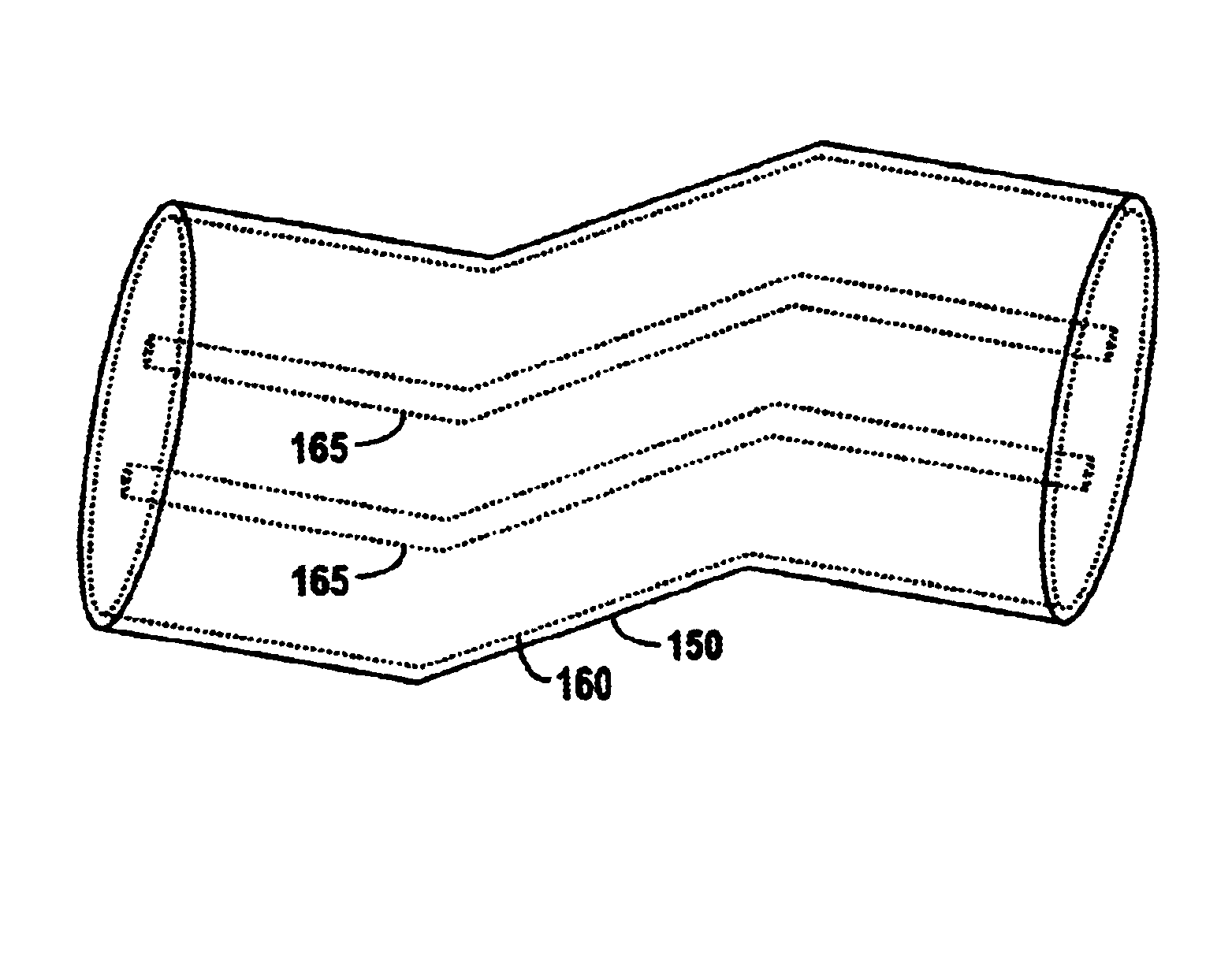
[0022]FIG. 5 is a block diagram of an ac energy delivery system 100 according to one embodiment of the present invention. AC energy delivery system 100 includes a matching network 110a that inductively couples an ac power source 120 to a load 130, such as a plasma processing chamber. The ac power source is coupled to a transmission line 140a to deliver ac energy to the transmission line. Transmission line 140a is inductively coupled to a second transmission line 140b. Transmission line 140b is further coupled to the load 130. Transmission line 140b inductively receives ac energy from transmission line 140a and further delivers the ac energy to the load 130. The mutual inductance of two transmission lines is proportional to the length of both of the transmission lines and inversely proportional to the distance between them. To effectively control the mutual inductance of the two transmission lines 140a-b they are placed within close proximity of each other and are enclosed within a s...


PUM


Abstract

An apparatus and method for maximizing ac energy delivered to a load by minimizing energy reflected from a load, such as an RF power source coupled to a plasma load for substrate processing chambers, including a matching network, wherein the matching network couples an ac power source and load. The matching network having two transmissions lines that are inductively coupled for a fixed portion of their length, such length being at least one wavelength of the ac energy generated by the ac power source. The matching circuit providing continuously variable impedance matching through the use of fixed components.

Description

BACKGROUND OF THE INVENTION[0001]The present invention relates to a matching circuit that reduces power reflected from a plasma formed in a substrate processing chamber. The invention is useful in a variety of technologies but is particularly useful in the manufacture of integrated circuits.[0002]Plasma processing is a common step in the manufacture of integrated circuits. Common plasma processing steps include plasma enhanced chemical vapor deposition, reactive ion etching, and sputter etching among others. In such plasma processing steps, precise control of the plasma can be important in order to meet the manufacturing requirements of today's integrated circuits.[0003]Typically a plasma is generated by applying RF energy to a coil or plates of a capacitor (inductive vs. capacitive coupling). To efficiently couple RF energy into a substrate processing chamber matching networks have been used to minimize the energy reflected from a plasma back into the RF generator. The source imped...

Claims


Application Information

Patent Timeline
Patent Type & Authority Patents(United States)
IPC IPC(8): H03H7/38
CPCH03H7/38
Inventor TANAKA, TSUTOMUWOLFF, STEFAN A.
Owner APPLIED MATERIALS INC
Why Eureka
Try Eureka