Proximity sensor with adaptive threshold

a threshold and sensor technology, applied in the field ofproximity sensing systems and methods, can solve the problems of battery power of devices, significant periods of idle time, and increased demand for longer intervals between battery replacement or recharging, and achieve the effect of false detection

Inactive Publication Date: 2005-08-23
MICROSOFT TECH LICENSING LLC
View PDF86 Cites 53 Cited by
  • Summary
  • Abstract
  • Description
  • Claims
  • Application Information

AI Technical Summary

Benefits of technology

[0013]According to another aspect of the invention, a second sensor (e.g., a second receptor / illuminating source pair) is added, and an object-near condition is not recognized unless both sensors detect the object. In this manner, false detections can be avoided when a user device (e.g., a computer mouse) is positioned next to a stationary object (e.g., a coffee cup or other desktop object). According to another aspect of the invention, the voltage sample series can be tested for noise or other anomalous results, and the series discarded if corrupted.

Problems solved by technology

While components of such devices are becoming increasingly power hungry, the demand for longer intervals between battery replacement or recharging has increased.
Indeed, many devices are often turned on for ready usability but left idle for significant periods of time.
Without effective power management, however, continuously operating a wireless peripheral can rapidly deplete the device's battery power, thereby requiring frequent battery replacement or recharging.
On the other hand, optical tracking requires considerable power for driving the circuitry used to illuminate a trackable surface and to receive and process light (image information) reflected from the trackable surface.
Although optical mice and other cursor control devices are an improvement over devices relying upon mechanical encoder wheels, sampling mouse motion as a method of “waking” a sleeping optical mouse is problematic.
This requires a motion detector's illuminating LED to be turned on for a significant amount of time.

Method used


Image

  • Proximity sensor with adaptive threshold
  • Proximity sensor with adaptive threshold
  • Proximity sensor with adaptive threshold

Examples


Embodiment Construction

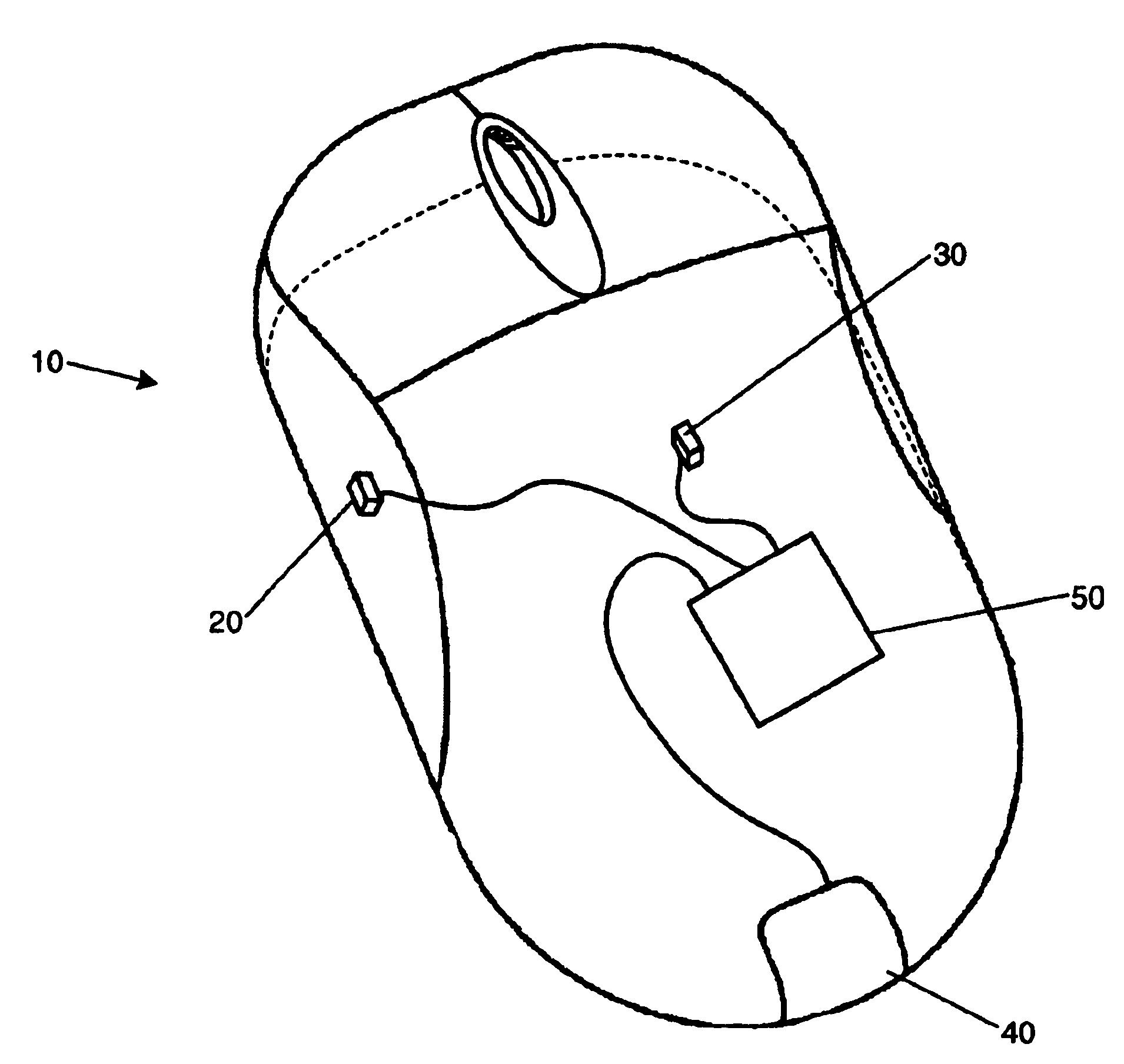
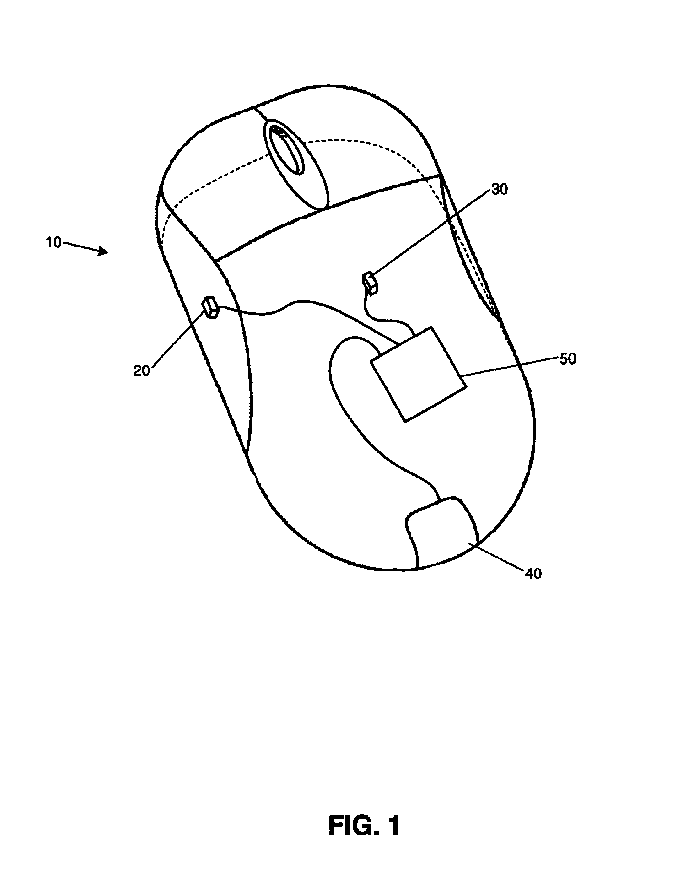
[0031]An exemplary application of the invention within a computer input device is presented. Specifically, a wireless, optically tracking computer mouse is described by way of example. However, the invention has much wider-ranging application, and can be used in numerous devices wherein it would be advantageous to conserve battery power during periods of non-use. The invention also has a useful application in other data input devices—portable and non-portable, wireless and wired, self-contained and peripheral (e.g., to a host computer). The invention finds particularly useful application (but is not limited to) battery powered devices which are intermittently used and generally left on over extended periods of time so as to provide ready usability when demand so requires. Such devices include (but are not limited to) portable computers, personal data assistants (PDAs), tablet computers, cellular phones, pagers and wireless computer peripherals, e.g., mice and keyboards. Moreover, th...


PUM


Abstract

A proximity sensor measures receptor output with an energy source deactivated. The sensor then measures receptor output with the energy source activated. The measurements with the energy source activated are compared to the measurements with the energy source deactivated to compensate for the effect of ambient conditions. A near condition is recognized if the change between the two groups of measurements exceeds a designated value. To compensate for receptor output that may decrease after reaching a peak value during approach of an object, a near condition can be maintained until the change between the two groups of measurements no longer exceeds a different designated value. Multiple sensors can be used to avoid false near conditions caused by, e.g., placing a device equipped with the sensors next to a stationary object. In one embodiment, a sensor comprises an infrared light emitting diode and a phototransistor.

Description

CROSS-REFERENCES TO RELATED APPLICATIONS[0001]This is a divisional of U.S. patent application Ser. No. 10 / 058,384, filed Jan. 30, 2002 (now U.S. Pat. No. 6,703,599), the contents of which are incorporated herein by reference in their entirety.FIELD OF THE INVENTION[0002]This invention relates to proximity sensing systems and methods. Such systems and methods are useful for managing power consumption in an electronic device, as well as for other purposes.BACKGROUND OF THE INVENTION[0003]Power management is becoming increasingly important as electronic devices place greater reliance on battery power. Portable computers, personal data assistants (PDAs), tablet computers, cellular phones, pagers, and wireless computer peripherals are only a few examples. While components of such devices are becoming increasingly power hungry, the demand for longer intervals between battery replacement or recharging has increased. Indeed, many devices are often turned on for ready usability but left idle...

Claims


Application Information

Patent Timeline
Patent Type & Authority Patents(United States)
IPC IPC(8): G06M7/00G09G5/08H01J40/14H01J40/00H04Q7/20G06F1/32G06F3/033
CPCG06F1/3203G06F1/3231G06F1/3259G06F3/03543Y02B60/148H03K2217/94026Y02B60/1253Y02B60/1289Y02D10/00
Inventor CASEBOLT, MARK W.LEE, MARK R.
Owner MICROSOFT TECH LICENSING LLC
Why Eureka
Try Eureka