Illumination apparatus, illumination-controlling method, exposure apparatus, device fabricating method

a technology of illumination control and exposure apparatus, which is applied in the direction of lighting and heating apparatus, printing, instruments, etc., can solve the problems of difficult to obtain optimal lithography process and desired resolution, and the configuration cannot partially modify the illumination condition of the mask plane. achieve the effect of high quality

Inactive Publication Date: 2005-08-23
CANON KK
View PDF8 Cites 52 Cited by
  • Summary
  • Abstract
  • Description
  • Claims
  • Application Information

AI Technical Summary

Benefits of technology

[0008]It is an exemplary object of the present invention to provide an illumination apparatus as well as an illumination-controlling method, an exposure apparatus, a de...

Problems solved by technology

However, the conventional configuration cannot partially modify the illumination condition for the mask plane.
As a consequence, the mask having two kinds of patterns should be il...

Method used


Image

  • Illumination apparatus, illumination-controlling method, exposure apparatus, device fabricating method
  • Illumination apparatus, illumination-controlling method, exposure apparatus, device fabricating method
  • Illumination apparatus, illumination-controlling method, exposure apparatus, device fabricating method

Examples


Embodiment Construction

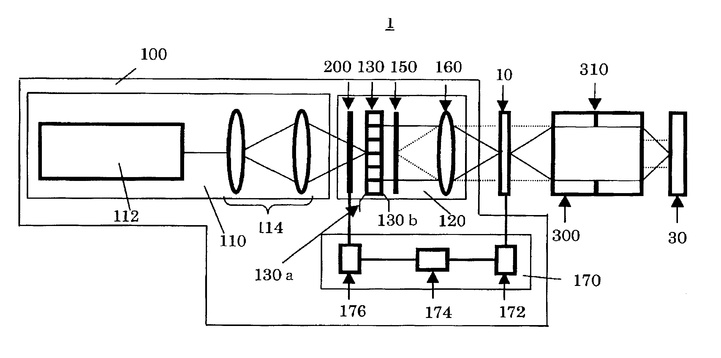
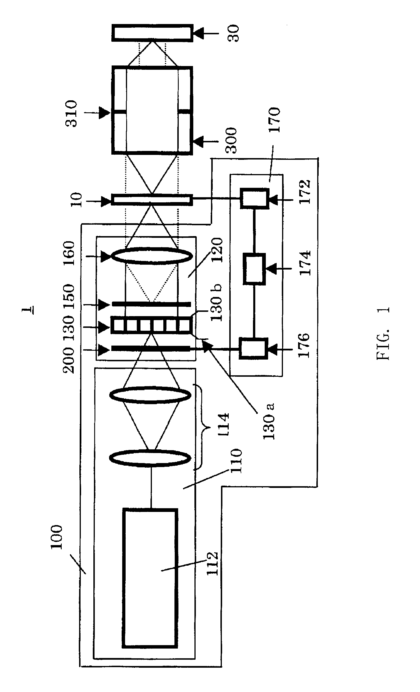
[0034]A description will now be given of an exposure apparatus 1 as one aspect of the present invention with reference to accompanying drawings. Here, FIG. 1 is a schematic sectional view of an exposure apparatus 1 of the present invention. As shown in FIG. 1, the exposure apparatus 1 includes a mask 10 on which a circuit pattern to be transferred is created, a plate 30, an illumination apparatus 100 that illuminates the mask 10, and a projection optical system 300. The exposure apparatus 1 of the present invention is especially effective when the plate 30 is a wafer that is used to fabricate a system chip in which a memory pattern and a logic pattern is mixed in one chip. However, the exposure apparatus 1 of the present invention does not preclude its application for an exposure process to fabricate memory chips.

[0035]The exposure apparatus 1 is a projection exposure apparatus that exposes onto the plate 30 the circuit pattern created on the mask 10, for example, in a step-and-repe...


PUM


Abstract

There is provided an illumination apparatus including an optical integrator including multiple optical systems for receiving light from a light source, and for producing multiple beams for illuminating a plane of mask or reticle on which a pattern is draw, a position of an incidence plane of the optical integrator and a position of the plane to be illuminated being arranged optically conjugate with each other, and a device for forming an optical characteristic distribution of light at the incidence plane, the light entering at least part of the multiple optical systems, whereby different areas on the plane of plane to be illuminated can be illuminated under different illumination conditions.

Description

BACKGROUND OF THE INVENTION[0001]The present invention relates generally to illumination apparatuses, and more particularly to an illumination apparatus for illuminating a reticle or a mask (these terms are used interchangeably in the present application) on which a pattern is drawn, in an exposure apparatus for use with a photolithography process for fabricating semiconductor devices, liquid crystal display devices, image pick-up devices (CCD, and the like), thin-film magnetic heads, and the like.[0002]Recent fine and highly integrated circuit patterns have required wafers with a critical dimension of 0.3 μm or less, and accordingly the lithography process has mainly used a projection exposure apparatus so as to meet this requirement. Generally, a projection exposure apparatus includes an illumination optical system for illuminating a mask, and a projection optical system, located between the mask and an object to be exposed, for projecting a pattern on the illuminated mask onto th...

Claims


Application Information

Patent Timeline
IPC IPC(8): G03F7/20G02B19/00H01L21/027
CPCG03F7/70075G03F7/70108
Inventor TERASHI, TAKAAKI
Owner CANON KK
Why Eureka
Try Eureka