Method of making channel-aligned resonator devices

a resonator device and channel-aligned technology, applied in the field of laser devices, can solve the problems of not being able to achieve high-quality production of a given frequency channel, and the current fabrication technique cannot meet the requirements of high-quality lasers

Inactive Publication Date: 2005-08-23
SPARKOLOR CORP +1
View PDF20 Cites 33 Cited by
  • Summary
  • Abstract
  • Description
  • Claims
  • Application Information

AI Technical Summary

Problems solved by technology

The growth of demand for subscriber bandwidth has led to great pressure to expand the capacity of the telecommunications networks.
However, current fabr

Method used


Image

  • Method of making channel-aligned resonator devices
  • Method of making channel-aligned resonator devices
  • Method of making channel-aligned resonator devices

Examples


embodiment

Laser Embodiment

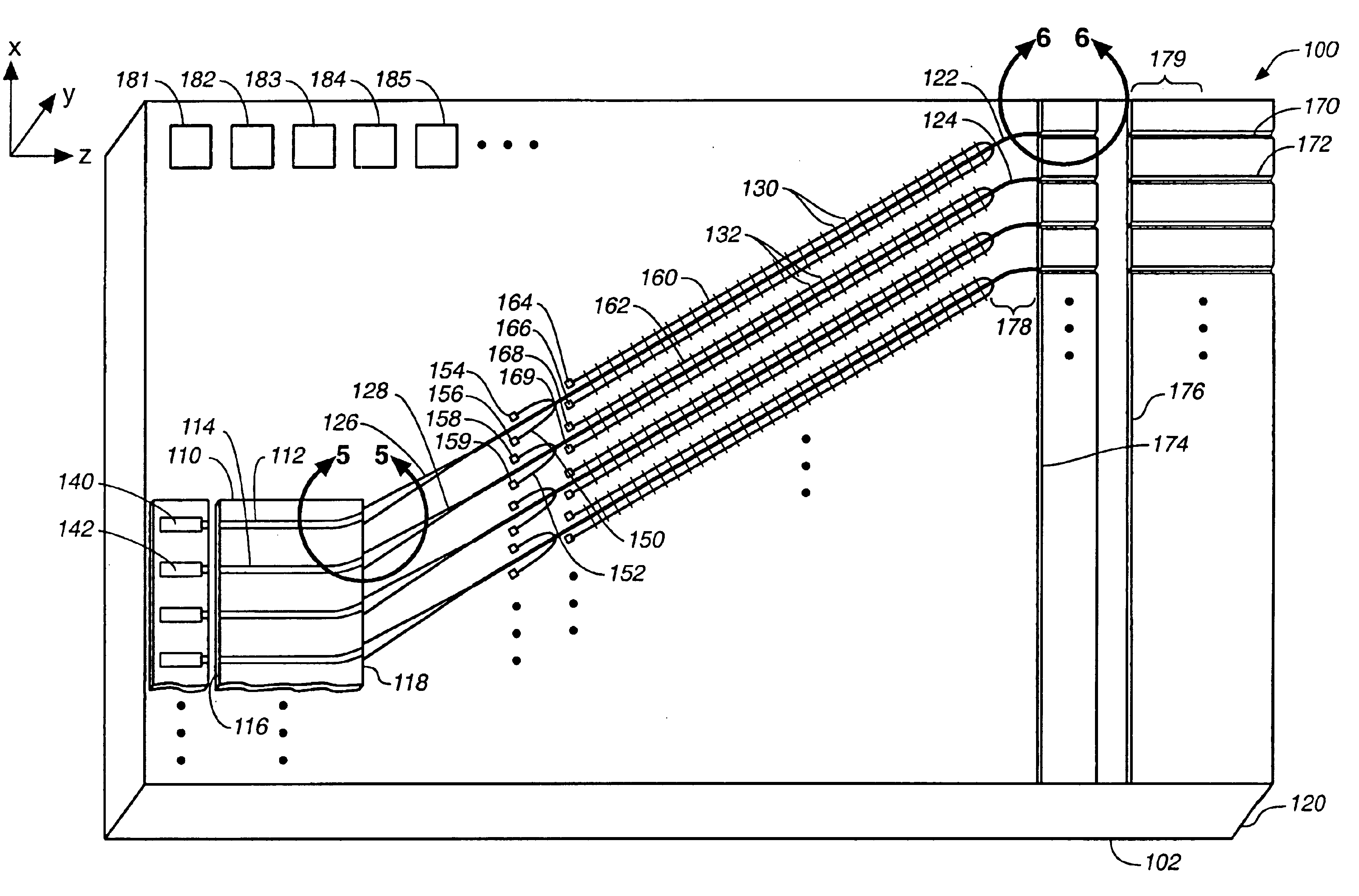
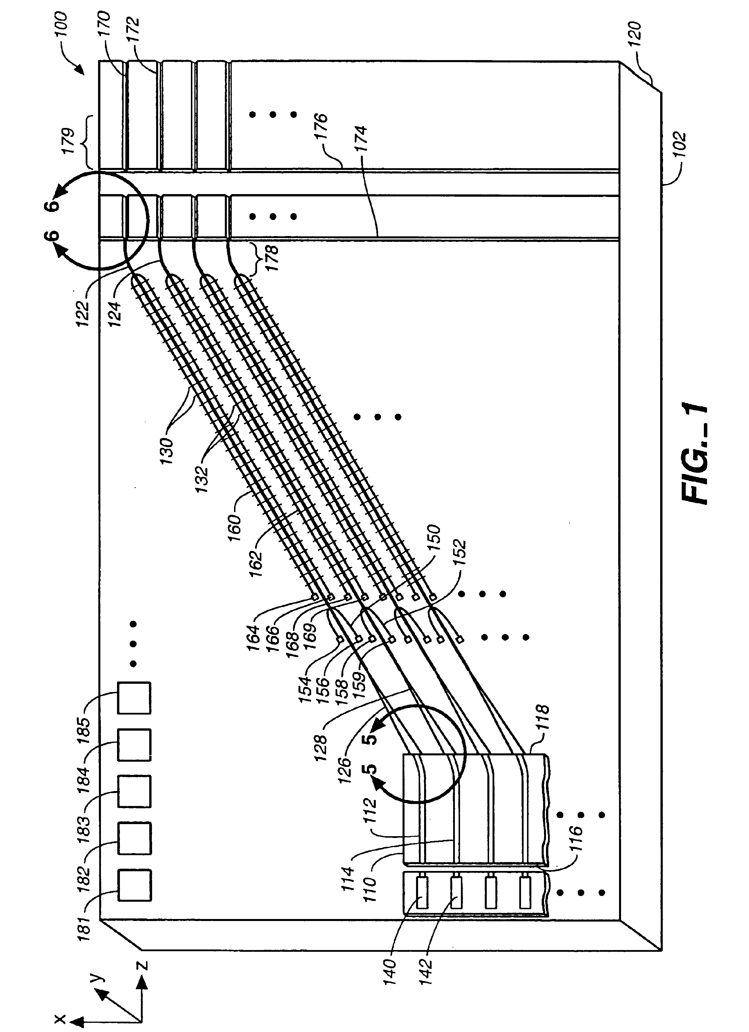
[0044]FIG. 1 shows a preferred embodiment of the hybrid tunable laser chip 100. A semiconductor laser chip 110 is flip-chip bonded to the substrate chip 120 producing a hybrid of two integrated waveguide chips. The laser chip is preferably fabricated from InP so that it emits in the 1550 nm region or the 1310 nm region. The waveguides 112 and 114 provide optical amplification when excited by sufficient injection current, over an operating band of optical frequencies including a desired wavelength such as 1550 nm or 1310, 980, 860, 780, 630, or 500 nm, or another useful wavelength region. For a 1550 nm laser, a typical gain bandwidth would be about 50 nm (such as from 1520 to 1570 nm or from 1560 to 1610 nm), and would overlap a portion of the amplifying bandwidth of the Er-doped fiber amplifier either in the conventional band or one of the extended operating bands. The gain bandwidth may be smaller for lower injection current, or as large as 120 nm or more for high i...


PUM


Abstract

A method of making permanent adjustments to the resonant cavity of a laser device in order to match its free spectral range to a specified frequency interval involves monitoring the optical output produced during laser operation or cavity illumination with diagnostic light, determining the free spectral range from the monitored output, and then permanently modifying the effective refractive index of an intracavity waveguide segment of the laser device according to the determined free spectral range obtained from the monitoring step until the desired match is achieved. The permanent index changes can be done in several ways, including illumination of the intracavity segment with an energetic beam (e.g. UV light) to induce a chemical alteration in the waveguide material, such as polymer cross-linking in the waveguide cladding. Evaporative deposition or ablative removal of intracavity waveguide material would also produce the desired permanent modifications.

Description

TECHNICAL FIELD[0001]This invention relates to laser devices that produce optical energy of tightly controlled optical frequency, particularly for use in telecommunications applications. More particularly, the invention relates to devices that produce a specified optical frequency independent of thermal variations, while possessing the ability to be tuned or switched among alternative optical frequencies by thermal, electric field, or other control means without modifying the specified frequencies.BACKGROUND ART[0002]This invention relates to laser devices that produce optical energy of tightly controlled optical frequency, particularly for use in telecommunications applications.[0003]More particularly, the invention relates to devices that produce a specified optical frequency independent of thermal variations, while possessing the ability to be tuned or switched among alternative optical frequencies by thermal, electric field, or other control means without modifying the specified...

Claims


Application Information

Patent Timeline
IPC IPC(8): H01S3/03H01S5/00H01S5/02H01S5/06H01S5/0683H01S5/14H01S5/40
CPCH01S5/0607H01S5/4062H01S5/005H01S5/02248H01S5/02272H01S5/0683H01S5/101H01S5/1014H01S5/1082H01S5/141H01S5/4087H01L2224/48091H01L2224/48247H01L2924/00014H01S5/02325H01S5/0237
Inventor DEACON, DAVID A. G.
Owner SPARKOLOR CORP
Why Eureka
Try Eureka