Variable optical attenuator having waveguides and MEMS actuator

Active Publication Date: 2005-08-23
SAMSUNG ELECTRONICS CO LTD
View PDF13 Cites 2 Cited by
  • Summary
  • Abstract
  • Description
  • Claims
  • Application Information

AI Technical Summary

Benefits of technology

[0019]According to the present invention, since components of the variable optical attenuator can be configured on a boar

Problems solved by technology

It is very difficult to achieve the precision and guarantee the reliability.
That is, changing ambient temperatures surrounding the el

Method used


Image

  • Variable optical attenuator having waveguides and MEMS actuator
  • Variable optical attenuator having waveguides and MEMS actuator
  • Variable optical attenuator having waveguides and MEMS actuator

Examples


Example

[0030]Preferred embodiments of a variable optical attenuator according to the present invention will be described in detail with reference to the accompanying drawings.

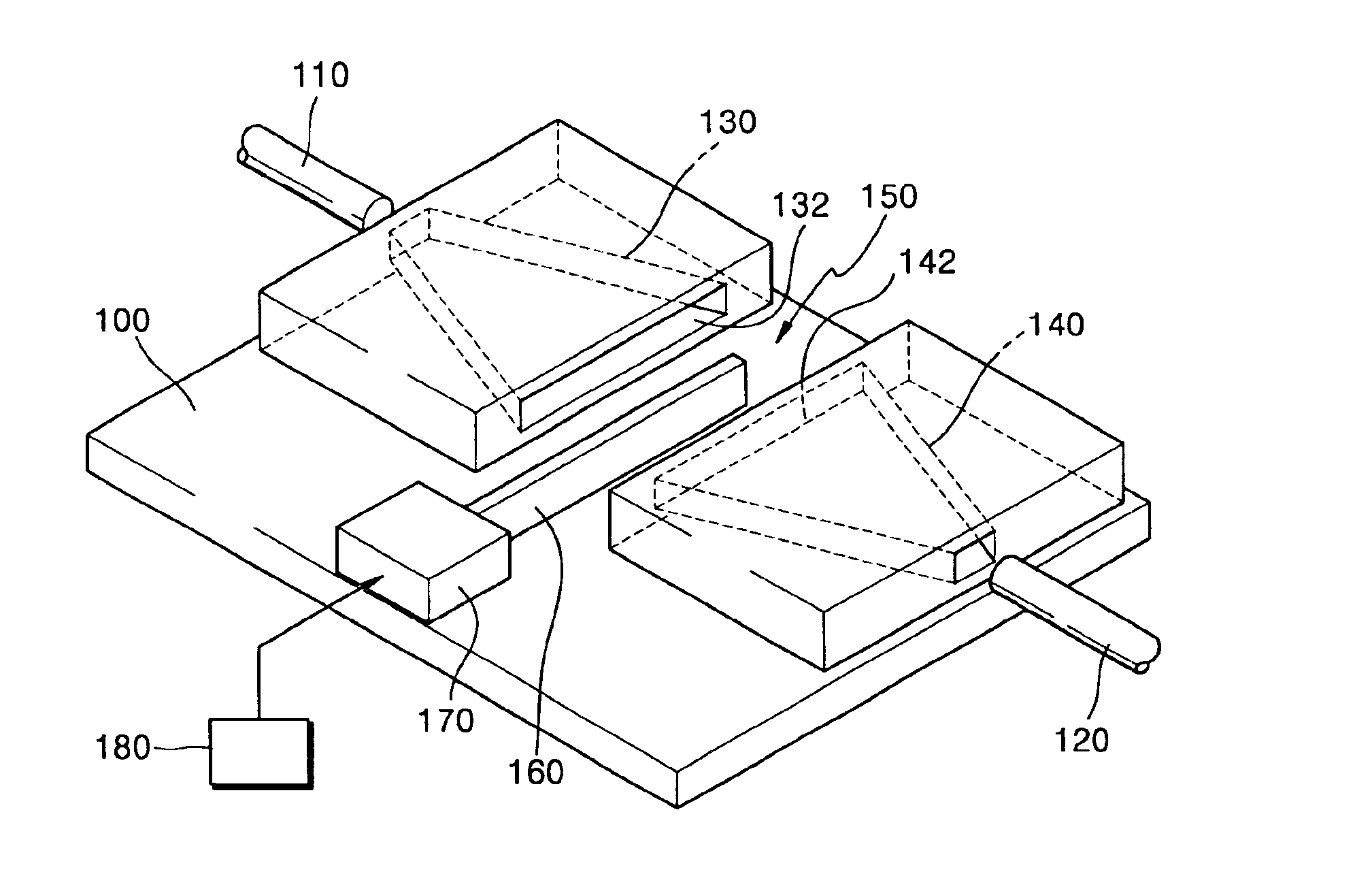
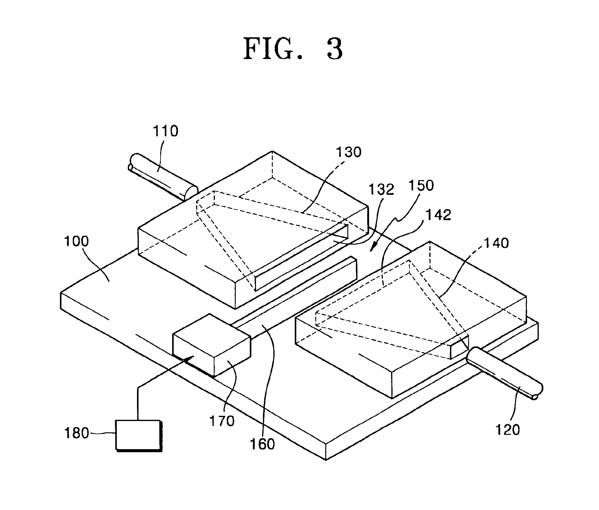
[0031]FIG. 3 is a perspective view showing the configuration of the variable optical attenuator according to the first embodiment of the present invention.

[0032]With reference to FIG. 3, the variable optical attenuator according to the present invention includes an input waveguide 130, an output waveguide 140, an optical shutter 160 and a microelectromechanical system (MEMS) actuator 170 for moving the optical shutter.

[0033]The input waveguide 130 implemented on a board 100 increases in width along the optical path. That is, the width of the input waveguide 130 increases linearly from one end adjacent to the optical fiber 110 of the input end to the other end adjacent to the opening 132. Therefore, the light entering through the optical fiber 110 of the input end to the input waveguide 130 is expanded and output from ...


PUM


Abstract

A variable optical attenuator having a waveguide and an MEMS actuator. In the variable optical attenuator, the input waveguide and the output waveguide face each other and are separated by a gap. The input waveguide increases in width along an optical path in order to expand the width of the light entering through an optical fiber of the input end. The output waveguide decreases in width along the optical path in order to make the expanded light converge towards the optical fiber of the output end. The optical shutter moves in the space between the two waveguides under the control of the MEMS actuator and attenuates the amount of the light. The variable optical attenuator having such configuration can be mass-produced in array form and are unaffected by ambient temperature changes.

Description

BACKGROUND OF THE INVENTION[0001]1. Field of the Invention[0002]The present invention relates to an optical attenuator, and more particularly, to a variable optical attenuator for attenuating the amount of the light transmitted through an optical fiber variably. The present application is based on Korean Patent Application No. 2001-61043, filed Sep. 29, 2001, which is incorporated herein by reference.[0003]2. Description of the Related Art[0004]As optical communication systems using optical fibers draw more attention, technologies related to optical communication devices or elements widely used in communication networks are under development proactively. As one of the optical communication elements, an optical attenuator attenuates a certain amount of the incident light and outputs the attenuated light. The optical attenuator includes a fixed optical attenuator which attenuates a fixed amount of the light, and a variable optical attenuator which attenuates a variable amount of the l...

Claims


Application Information

Patent Timeline
IPC IPC(8): G02B6/35G02B6/26G02B6/122G02B6/12G02B6/00
CPCG02B6/122G02B6/266G02B6/353G02B6/3596G02B6/3552G02B6/3588G02B6/3594G02B2006/12145G02B2006/12195G02B6/00
Inventor KIM, SUNG-CHUL
Owner SAMSUNG ELECTRONICS CO LTD
Why Eureka
Try Eureka