
Layout methodology and system for automated place and route

a technology of automated place and route, applied in the direction of cad circuit design, program control, instruments, etc., can solve the problems of complex floor plan, poor efficiency of p&r tools, and various layout schemes for foregoing related art, so as to reduce the layout schedule, reduce the amount of human resources, and reduce the effect of layout schedul

Inactive Publication Date: 2005-08-23
TERACHIP
View PDF11 Cites 21 Cited by
  • Summary
  • Abstract
  • Description
  • Claims
  • Application Information

AI Technical Summary

Benefits of technology

[0011]It is an object of the present invention to significantly reduce the layout schedule (e.g., to 4 months), and the layout implementation complexity for SOC technology.
[0013]It is also an object of the present invention to develop a robust, simple, and reusable place and route method, without any limitation based on chip block type, size or number of blocks.

Problems solved by technology

The related art SOC have become bigger, and may include tens of millions of transistors that result in very complex floor planning, with many sub blocks in a hierarchy.
However, in SOC, the efficiency of the P&R tools is very poor if they are used for millions of cells as one hierarchy.
However, the foregoing related art layout scheme has various problems and disadvantages.
For example, but not by way of limitation, a substantial amount of layout work is needed to build the chip layout in hierarchy or by sub blocks, and significant human resources are required.
Those related art approaches result in a relatively long work process, until the related art SOC layout is completed.
These related art approaches depend on at least chip size, speed of operation, complexity of the integration and amount of routing and power consumption.
As a result, there are at least the following disadvantageous bottlenecks.
First, each sub block is designed as a separated stand-alone unit, which results in overhead.
As a result, a non-optimum layout of resources is produced (e.g., in terms of area, pins location and routing resources).
Additionally, there is a related art problem when combining all sub blocks together, which results in a layout penalty due to the blocks.
Also, input / output (IO's) and IP cell integration usually require a relatively long time.
With related art method and P&R tools, a team of 8 Engineers will need to work for 6 months to complete the layout of the VLSI chip, which is a disadvantage of the related art.

Method used


Image

  • Layout methodology and system for automated place and route
  • Layout methodology and system for automated place and route
  • Layout methodology and system for automated place and route

Examples


Embodiment Construction

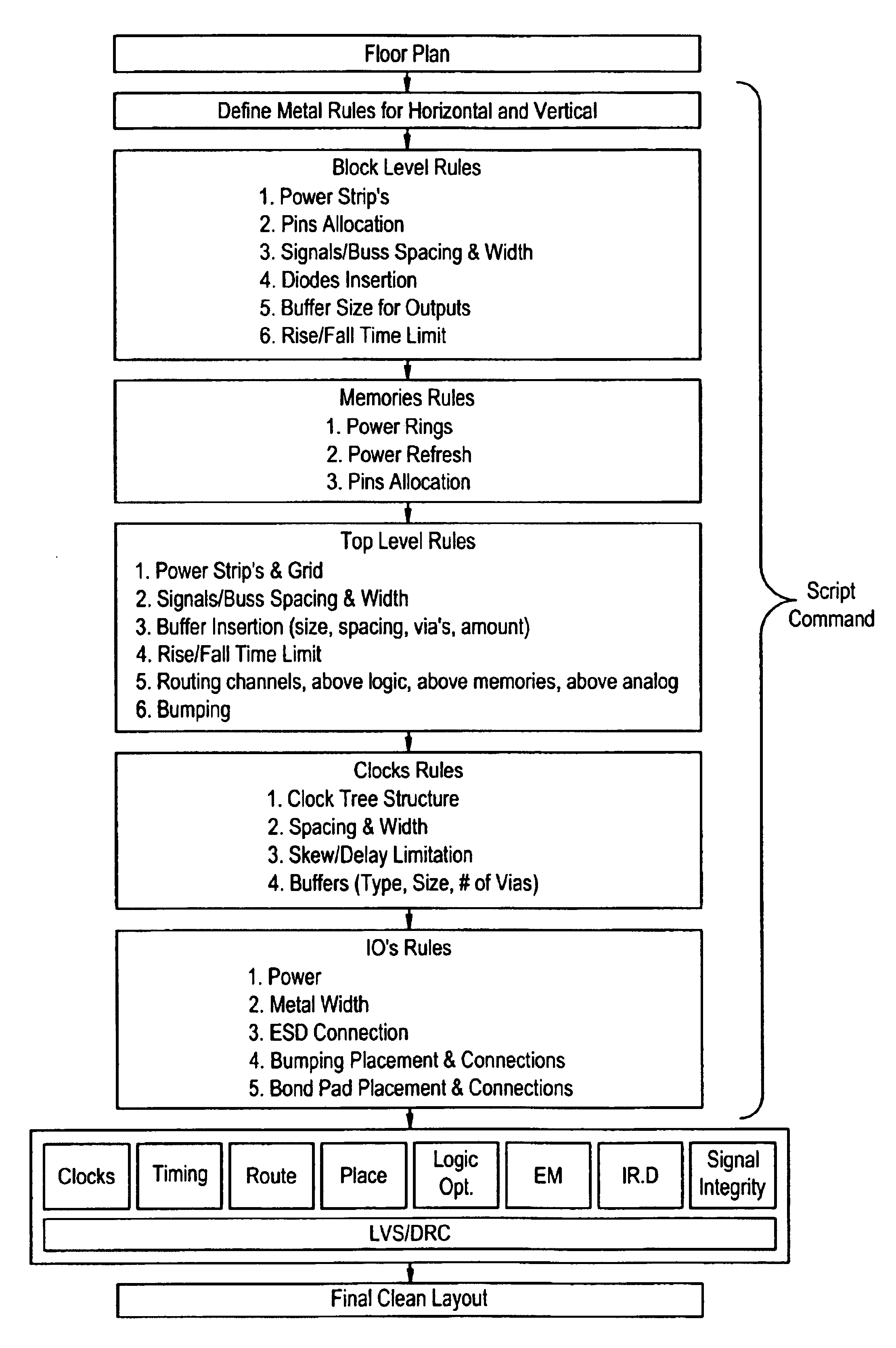
[0020]To achieve at least the foregoing objects, a simple, novel and unique layout methodology is provided for a fully automated place and route (P&R) tool, that permits building of a SOC layout that previously required many sub blocks in the related art. The present invention operates in a very efficient way that can result in better than ⅙ (e.g., average of about 1 / 10) of the time and cost comparing to the related art layout methodologies used in by today's ASIC vendors to implement SOC VLSI chips.

[0021]The novel method according to the present invention meets the requirements of very fast time to market with a limited human resources, and targets 0.13 um process (Deep Sub Micron).

[0022]The novel methodology of the present invention saves time and resolves, by design, the related art sub micron technology issues. The present invention is fully compatible with standard P&R tools, and covers sub micron (e.g., 0.13 um) process issues, including (but not limited to) Timing and Cross T...


PUM


Abstract

A new simple novel Layout methodology for high integration VLSI chip is proposed, which is reduced dramatically the complexity, the cost and the schedule for implementing a complex chip such as System On a Chip (SOC) that required hierarchical layout implementation. A set of rules is provided for the place and route process.

Description

[0001]This application claims benefit to provisional U.S. Application Ser. No. 60 / 443,847, filed on Jan. 31, 2003, the contents of which are incorporated herein by reference.BACKGROUND OF THE INVENTION[0002]1. Field of the Invention[0003]The present invention relates to a method and system for performing automated placing and routing (P&R). More specifically, the present invention relates to a set of rules for improving the process of conducting automated place and route.[0004]2. Related Art[0005]In the related art System On a Chip (SOC), and for other big chips built in very large scale integration (VLSI), cost and time to market are very important criteria for determining effectiveness. The related art SOC have become bigger, and may include tens of millions of transistors that result in very complex floor planning, with many sub blocks in a hierarchy. Accordingly, a different approach is needed for the layout implementation for the larger related art SOC, as compared with a compl...

Claims


Application Information

Patent Timeline
Patent Type & Authority Patents(United States)
IPC IPC(8): G06F9/45G06F17/50G06F9/455
CPCG06F17/5068G06F30/39
Inventor PAUL, GIDEONGRIGORYANTZ, EVGENY
Owner TERACHIP
Learn More