Method of producing a battery-connecting plate

a technology of connecting plate and battery, which is applied in the direction of multi-conductor cable end pieces, coupling device connections, propulsion parts, etc., can solve the problems of high production cost of l-shaped busbars and their administration, dangerously exposed wires at many portions, and complicated protection structures. , to achieve the effect of less exposed to the outside, safe and easy mounting

Inactive Publication Date: 2005-08-30
YAZAKI CORP
View PDF29 Cites 55 Cited by
  • Summary
  • Abstract
  • Description
  • Claims
  • Application Information

AI Technical Summary

Benefits of technology

[0019]This invention has been accomplished to overcome the above drawbacks and an object of this invention is to provide a battery-connecting plate which has integrally incorporated therein by insert molding battery-connecting

Problems solved by technology

On the other hand, the connecting plate 100′ of FIG. 19 requires L-shaped busbars 102′ of different sizes, and hence is disadvantageous in the production cost of the L-shaped busbars and their administration.
Due to the bulky member of the fuse casing 107, 107′ interposed, however, such a protection structure will inevitably become complicated.
Further, the wires are dangerously exposed at many portions.
In addition, due to the intersecting main power wires 112 and voltage detecting circuit constituting wires 106, the wiring becomes complicated so as to cause an impro

Method used


Image

  • Method of producing a battery-connecting plate
  • Method of producing a battery-connecting plate
  • Method of producing a battery-connecting plate

Examples


Embodiment Construction

[0062]Embodiments of this invention will now be described with reference to the attached drawings.

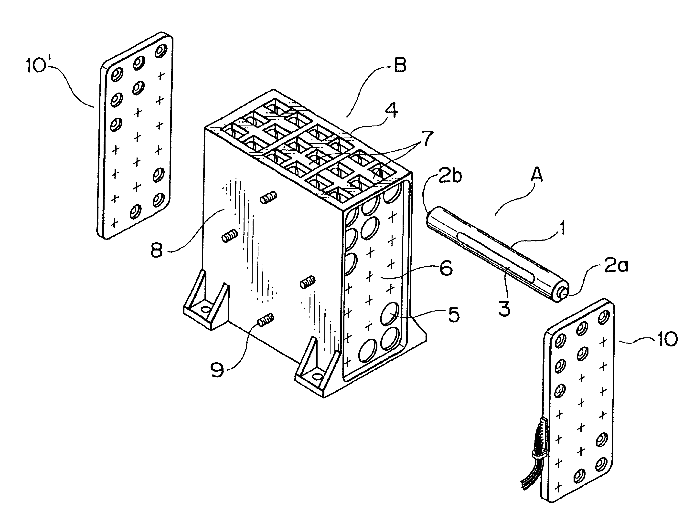
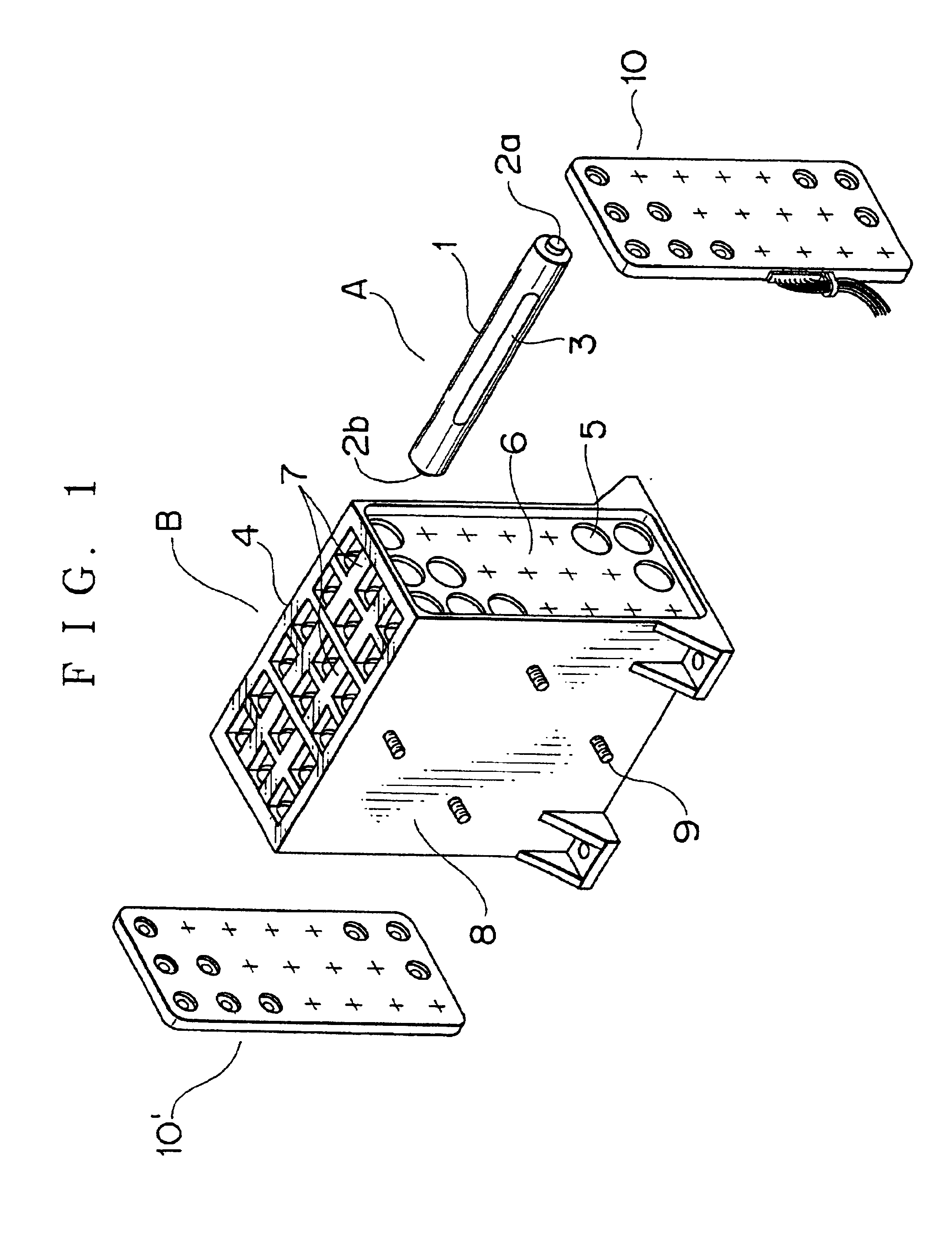
[0063]In FIG. 1, denoted A is a long cylindrical battery used as in an electric vehicle and B is a battery holder for receipt therein of a plurality of the batteries A. The battery A includes a main body 1, female-thread nut type positive and negative electrodes 2a, 2b provided at opposite ends of the main body 1, and a PTC element 3 secured to the outer periphery of the main body for checking the generation of heat from the battery A. The battery holder B consists of a rectangular parallelepiped frame body 4 and connecting plates 10, 10′ assembled at opposite sides of the frame body. The frame body 4, in the illustrated example, includes a plurality of support plates 6, each having a total of 21 (7 by 3) battery insertion holes 5, stays 7 which hold the support plates 6 in a parallel arrangement with one another, and major walls 8 one of which is provided with bolts 9 for fastening the...


PUM

PropertyMeasurementUnit
Electric potential / voltageaaaaaaaaaa

Abstract

A method of producing a battery-connecting plate by providing busbars which connect batteries together, attaching terminals to one end of wires to produce terminal-attached wires for detecting voltage of desired ones of the batteries, placing the terminal-attached wires in a predetermined layout in a wire protector, setting the busbars and wire protector in a mold with the burbars positioned corresponding to an arrangement of the batteries, injecting resin into the mold to produce a molded piece with the burbars and the terminal-attached wires therein, and cutting an element mount portion of each of the terminals and connecting a respective circuit protector element to the element mount portion in a bridging manner across the cut.

Description

[0001]This application is a division of prior application Ser. No. 09 / 413,242 filled Oct. 7, 1999 now U.S. Pat. No. 6,346,011.BACKGROUND OF THE INVENTION[0002]1. Field of the Invention[0003]This invention relates to a battery-connecting plate for use with a battery holder which receives a large number of cylindrical batteries and which is mounted as in an electric vehicle, a method of producing same, and a wire protector.[0004]2. Description of the Related Art[0005]A battery-connecting plate 100 as shown in FIGS. 18A, 18B is conventionally used as a means of connecting a plurality of batteries in series or in parallel.[0006]The connecting plate 100 includes a molded resin plate 103, a busbar 102 for connecting two batteries 101, fixed in the resin plate 103 by molding, the two batteries having nut-type positive and negative electrodes 101a, 101b, and a hexagonal and a square windows 103a, 103b in which electrode-connecting busbar holes 102a are exposed. The connection of the two bat...

Claims


Application Information

Patent Timeline
IPC IPC(8): H01M10/42H01R11/28H01M2/10H01R11/11H01M10/48H01M2/20H01M6/00H01M6/50B60K1/04G01R31/36H01M50/213H01M50/244H01M50/262H01M50/298H01M50/50H01M50/505H01M50/569
CPCH01M2/1077H01M2/20H01M2/206H01M10/4207H01M10/482H01R11/288H01M2/1083Y10T29/49117H01M2200/106H01R11/289Y10T29/49144Y10T29/49169Y10T29/49121Y10T29/49171Y10T29/49172Y02E60/10H01M50/50H01M50/213H01M50/262H01M50/244H01M50/505H01M50/569H01M50/298
Inventor IKEDA, TOMOHIRO
Owner YAZAKI CORP
Why Eureka
Try Eureka