Prefabricated insulation for HVAC ductwork and other fluid conduits

a technology of ductwork and fluid conduit, which is applied in the field of thermal insulation, can solve the problems of difficult to completely reach, difficult to cut, and high cost of job site cutting, and achieve the effects of improving insulation installation, reducing costs, and increasing the quality of installation

Inactive Publication Date: 2005-08-30
BUCHANAN SR MARVIN C
View PDF33 Cites 23 Cited by
  • Summary
  • Abstract
  • Description
  • Claims
  • Application Information

AI Technical Summary

Benefits of technology

[0028]It is hoped that the present invention will improve insulation installation, both by reducing costs and increasing the quality of installation.

Problems solved by technology

The workman usually gets in a kneeling position, or down on hands and knees, as it is otherwise difficult to reach completely across the 4-foot width.
This job-site cutting method is very time consuming and strenuous, subjecting the workman to the possibility of strains and sprains as well as exposing the workmen and other job site personnel to airborne fibers.
These fibers may be both an epidermal irritant and a respiratory hazard.
On some larger construction projects, such as hospitals, the insulation of ductwork may take many months to complete.
Failure of the flare-door-type staple guns is common, and since many job sites are in remote locations, the failure of the staple gun delays work and increases costs.
Many times starting the peel of the release strip can be difficult and take time.
Cutting and applying tape takes considerable time, as access may be difficult and require stooping and reaching, as most applications are accomplished from ladders or scaffolds.
Also, removal and management of release strips takes time.
If the joints are not completely sealed on the insulation jacketing installed on duct (such as air conditioning duct, which operates at a temperature lower than ambient temperature), moisture may enter the insulation, making the insulation wet and ineffective.
This results in condensation drips that damage ceilings and interiors of buildings.
Molds may result from this wet insulation and wet surfaces, resulting in damage and an indoor air pollution problem.

Method used


Image

  • Prefabricated insulation for HVAC ductwork and other fluid conduits
  • Prefabricated insulation for HVAC ductwork and other fluid conduits
  • Prefabricated insulation for HVAC ductwork and other fluid conduits

Examples


Embodiment Construction

[0042]The accompanying drawings and the description which follows set forth this invention in its preferred embodiment. However, it is contemplated that persons generally familiar with insulation will be able to apply the novel characteristics of the structures illustrated and described herein in other contexts by modification of certain details. Accordingly, the drawings and description are not to be taken as restrictive on the scope of this invention, but are to be understood as broad and general teachings.

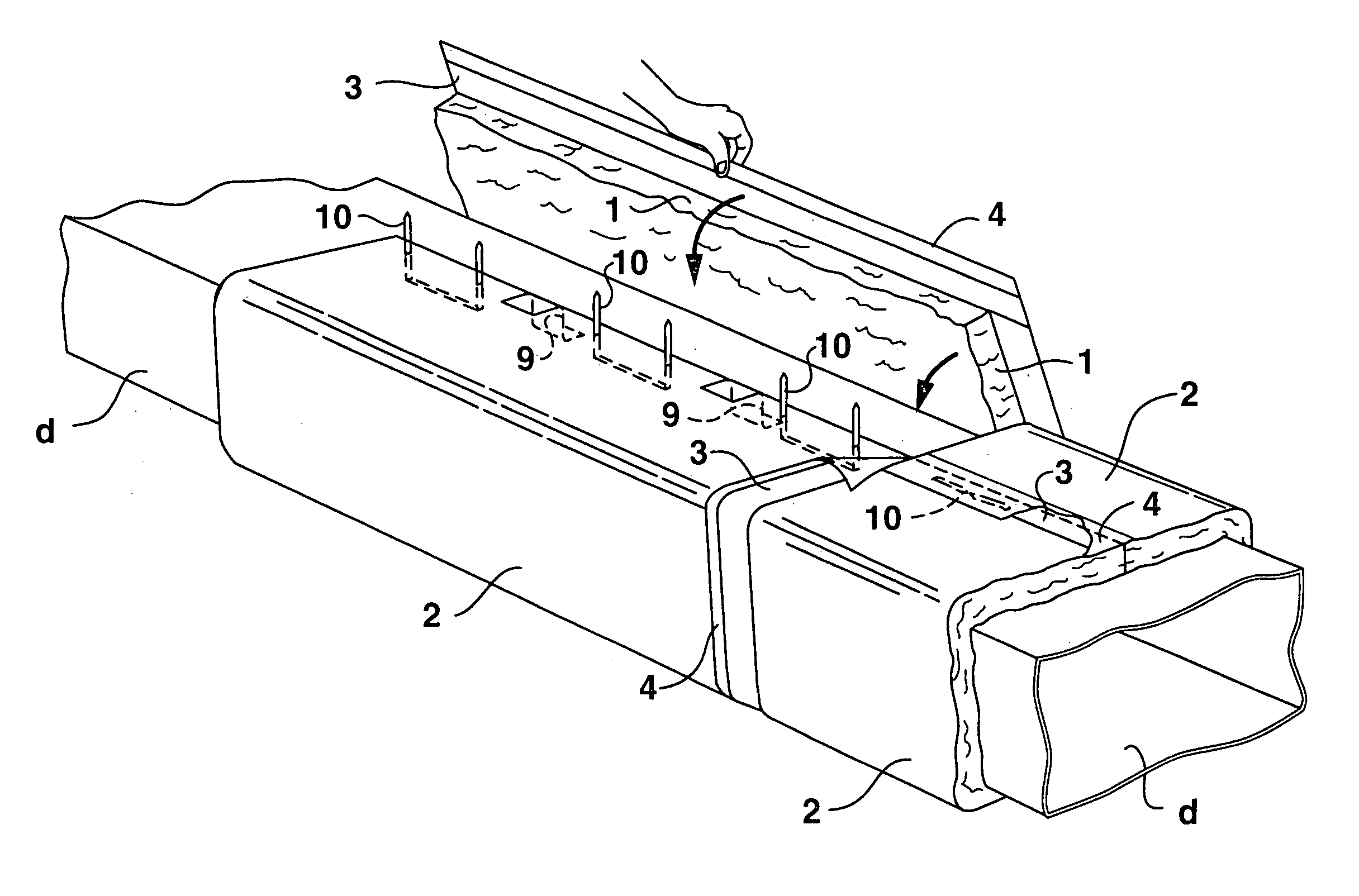
[0043]Referring now to the drawings in detail, wherein like reference characters represent like elements or features throughout the various views, a preferred embodiment of insulation constructed in accordance with the present invention is indicated generally in the figures by reference character 1.

[0044]The entirety of my earlier patent application Ser. No. 10 / 141,453, filed May 8, 2002, is hereby incorporated by referenced thereto.

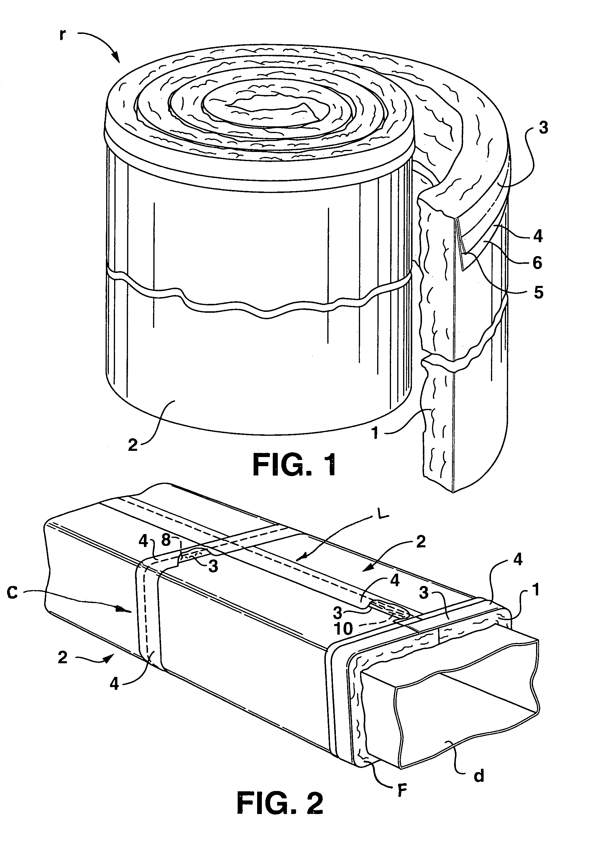
[0045]As shown in FIG. 1, a preferred embodime...


PUM


Abstract

An improved insulation and an improved method for preparing and installing sheets of insulation having a vapor-barrier jacket or “finish” to ductwork and other fluid conduits or other surfaces. Anchor tabs are provided on the insulation, as are also studs for anchorage and mechanical attachment. Pressure sensitive tape with a split release strip is applied to the sheets prior to the installation of the sheets to the ductwork or other fluid conduits. The pressure sensitive tape is for sealing of any penetrations in the vapor-barrier by the mechanical attachment devices and for sealing of the edge of the vapor barrier jacket flange to the adjacent piece vapor-barrier jacket. The insulation is configured such that during storage and shipment, the jacket attachment flanges are positioned to avoid crumpling.

Description

[0001]This application is a continuation-in-part of application Ser. No. 10 / 141,453, filed May 8, 2002 now abandoned.BACKGROUND OF THE INVENTION[0002]This invention relates generally to thermal insulation, and more specifically to fibrous blanket duct insulation or other forms and applications of insulation with vapor-barrier jackets.[0003]Fibrous blankets, also known as duct wrap, with vapor-barrier / finish jackets are one of the most widely used materials in the insulation of heating, air conditioning, and other conduits in buildings and industry. Standard fibrous blankets are packaged in rolls of 50 foot, 75 foot, or 100 foot lengths. The insulation width is typically 48 inches, and the jacket width is 50 inches, which includes the 2-inch wide jacket attachment-flange. Other widths or lengths may be available. The insulation is available in various thickness and densities. It is faced with a laminated jacket of foil, fiberglass strand reinforcement, and kraft paper or other membra...

Claims


Application Information

Patent Timeline
Patent Type & Authority Patents(United States)
IPC IPC(8): F16L59/02
CPCF16L59/026F24F13/0263Y10T428/14
Inventor BUCHANAN, SR., MARVIN C.
Owner BUCHANAN SR MARVIN C
Why Eureka
Try Eureka