Vehicle air conditioner with ejector refrigerant cycle

a technology of ejector and refrigerant cycle, which is applied in the field of air conditioners with ejector refrigerant cycles, can solve the problems of rapid defogment of windscreens, and achieve the effect of effective cooling, heating or dehumidification

Inactive Publication Date: 2005-08-30
DENSO CORP
View PDF15 Cites 18 Cited by
  • Summary
  • Abstract
  • Description
  • Claims
  • Application Information

AI Technical Summary

Benefits of technology

[0010]When the first and second throttles are further disposed in the refrigerant cycle for decompressing refrigerant in substantially iso-enthalpy, the switching unit is disposed to switch one of a cooling operation where the compartment is cooled, a dehumidifying and heating operation where the compartment is dehumidified while being heated, and a heating operation where the compartment is heated. In this case, in the cooling operation, refrigerant after being decompressed is evaporated in the interior heat exchanger to cool air passing therethrough, and high-pressure refrigerant discharged from the compressor is decompressed in the ejector while sucking gas refrigerant from the interior heat exchanger. In the dehumidifying and heating operation, refrigerant after being decompressed is evaporated in the interior heat exchanger to cool and dehumidify air passing therethrough, and high-pressure refrigerant discharged from the compressor is decompressed by the first throttle. Further, in the heating operation, high-temperature refrigerant before being decompressed flows into the interior heat exchanger to heat air passing therethrough, and the high-pressure refrigerant is decompressed in the second throttle. Accordingly, the compartment can be effectively cooled, heated or dehumidified while being heated.

Problems solved by technology

When the air conditioner is used for a vehicle, a windshield can be rapidly defogged even when the windshield is fogged.

Method used


Image

  • Vehicle air conditioner with ejector refrigerant cycle
  • Vehicle air conditioner with ejector refrigerant cycle
  • Vehicle air conditioner with ejector refrigerant cycle

Examples


first embodiment

[0025](First Embodiment)

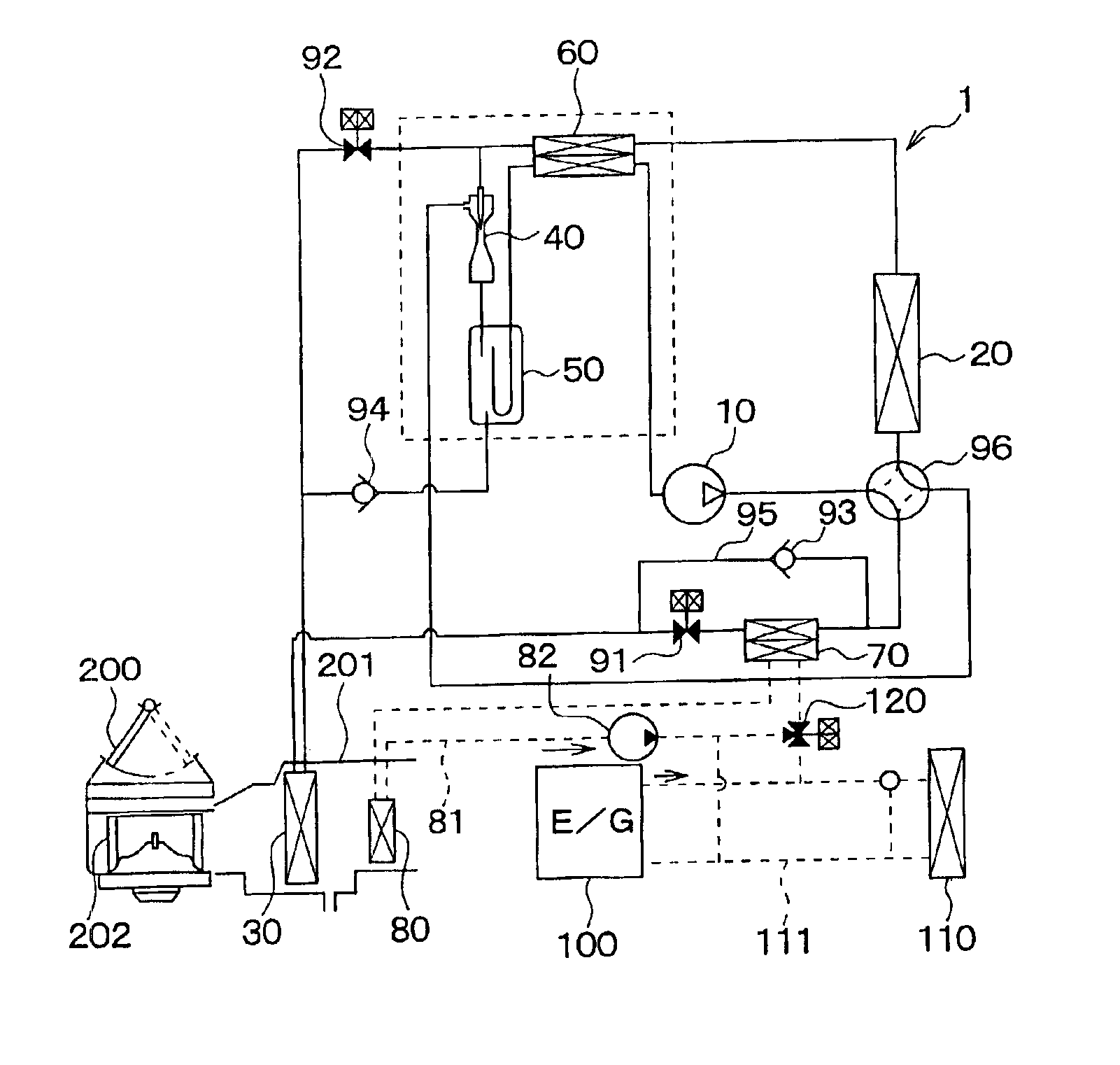
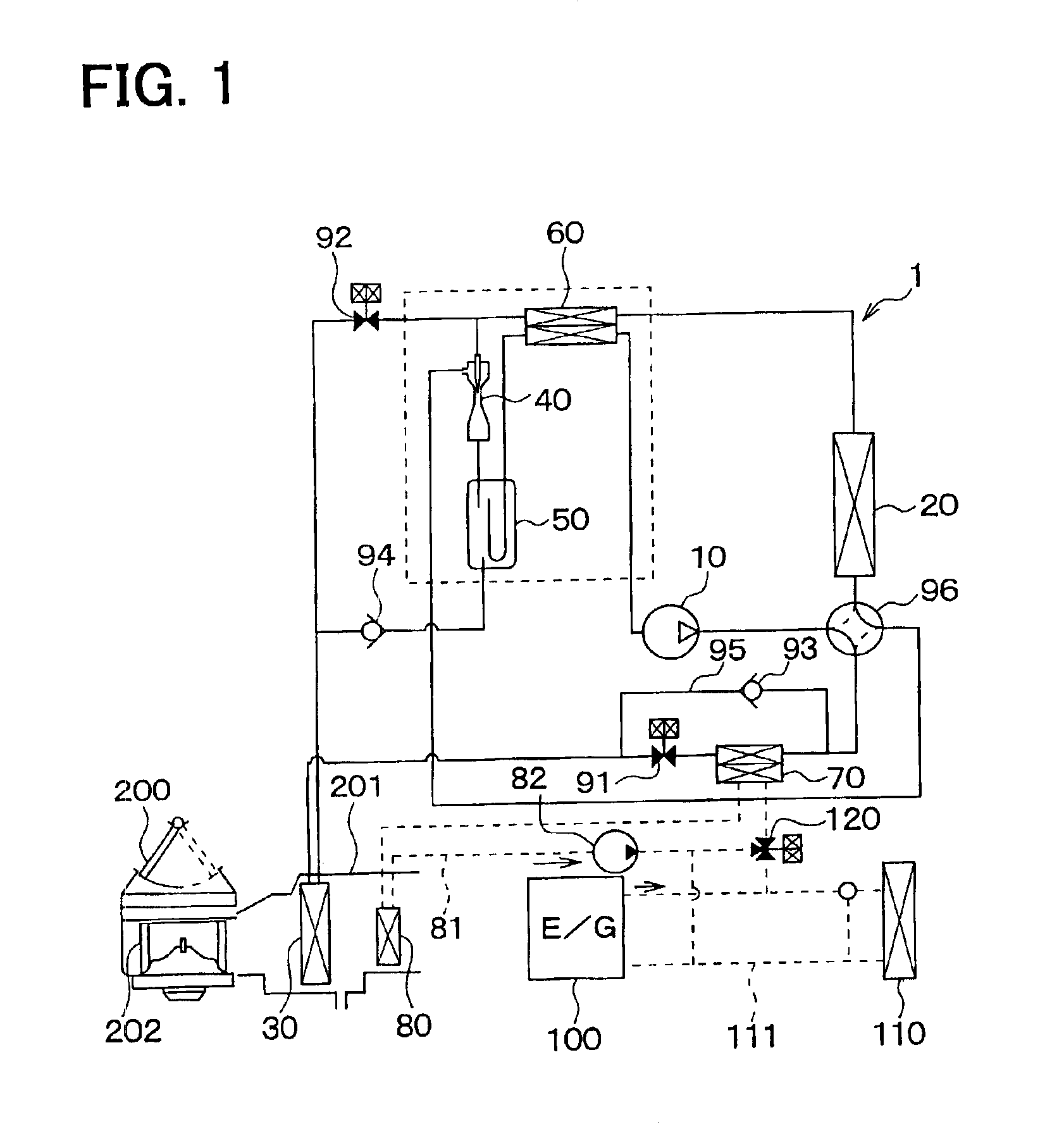
[0026]In the first embodiment, an air conditioner of the present invention is typically used for a vehicle. As shown in FIG. 1, the air conditioner includes a vapor-compression refrigerant cycle 1 having an ejector type decompression device. The refrigerant cycle 1 includes a compressor 10, an exterior heat exchanger 20, an interior heat exchanger 30, an ejector 40, a gas-liquid separator 50, an inner heat exchanger 60, a water-refrigerant heat exchanger 70, and a heater core 80.

[0027]The compressor 10 is a variable displacement compressor operated by a driving force from a driving engine, and is used as a pumping means for sucking and compressing refrigerant. The compressor 10 variably controls a displacement so as to absorb a variation of an engine speed and an air conditioning load. Here, the displacement means a theoretical displacement discharged from a discharge port of the compressor 10 by one rotation cycle of a shaft in the compressor 10.

[0028]In thi...

second embodiment

[0061](Second Embodiment)

[0062]The second embodiment is a modification of the first embodiment. Specifically, as shown in FIG. 5, the water-refrigerant heat exchanger 70 is disposed upstream from the switching valve 96 in the refrigerant flowing direction. In other words, the water-refrigerant heat exchanger 70 is disposed on the discharge side of the compressor 10 rather than the switching valve 96.

[0063]Although a refrigerant system of the second embodiment is modified, operation of the refrigerant system of the second embodiment is similar to that of the above-described first embodiment, and the advantage similar to the first embodiment can be obtained.

third embodiment

[0064](Third Embodiment)

[0065]In the dehumidifying and heating operation of the above-described first embodiment, the water-refrigerant heat exchanger 70 heats the engine-cooling water circulating through the heater core 80, so that the air to be blown into the compartment is heated indirectly by the high-temperature refrigerant as a heating source discharged from the compressor 10. In the third embodiment, as shown in FIG. 6, the interior heat exchanger 30 is used as a first interior heat exchanger, and a second interior heat exchanger 31 is disposed downstream from the interior heat exchanger 30 in the air flowing direction. The high-temperature refrigerant discharged from the compressor 10 is introduced in the second interior heat exchanger 31 so that the air to be blown into the compartment is heated directly by the second interior heat exchanger 31.

[0066]Next, characteristic operation and its effect of the air conditioner in this embodiment will be now described.
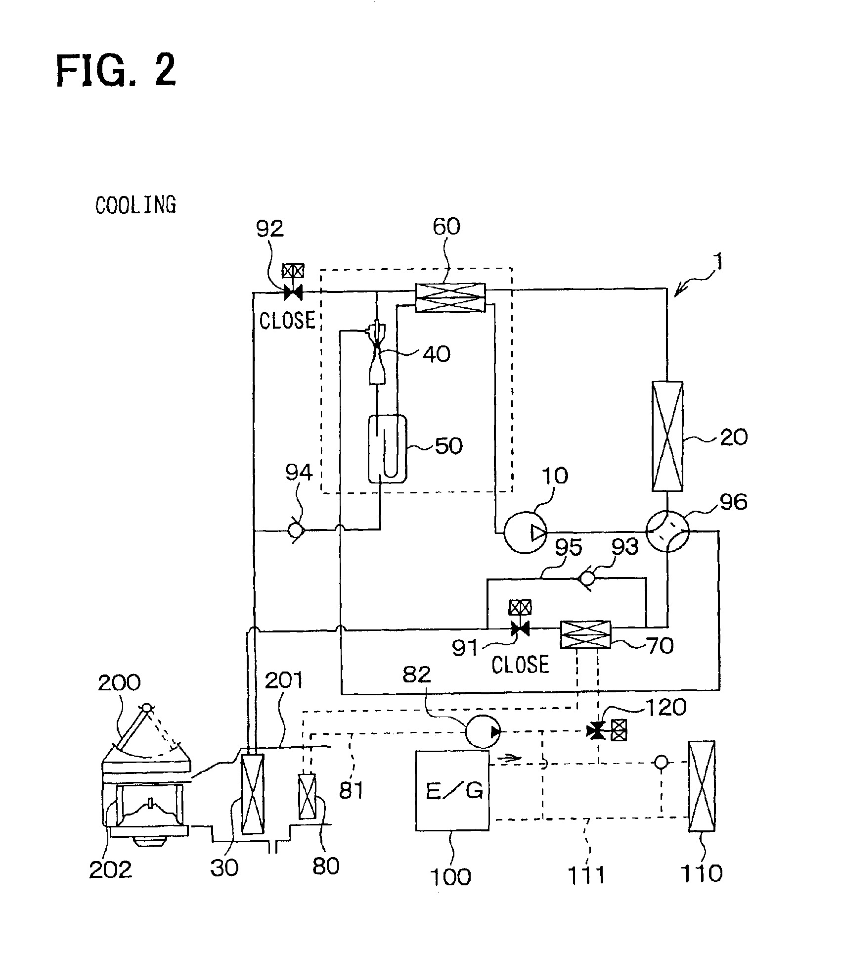
[0067]1. Coolin...


PUM


Abstract

An air conditioner includes a compressor for compressing refrigerant, an exterior heat exchanger for performing heat exchange between refrigerant and outside air, an interior heat exchanger for performing heat exchange between the refrigerant and air to be blown into the compartment, an ejector for decompressing high-pressure refrigerant, a heater core for heating air using a high-temperature fluid as a heating source, and a fluid-refrigerant heat exchanger that heats the fluid flowing to the heater core using high-temperature refrigerant discharged from the compressor as a heating source. In a dehumidifying and heating operation, refrigerant in the interior heat exchanger absorbs heat from air so that the air is cooled and dehumidified, and the dehumidified and cooled air can be further heated in the heater core by indirectly using the heating source from the high-temperature refrigerant.

Description

CROSS REFERENCE TO RELATED APPLICATION[0001]This application is based on Japanese Patent Application No. 2002-126403 filed on Apr. 26, 2002, the disclosure of which is incorporated herein by reference.BACKGROUND OF THE INVENTION[0002]1. Field of the Invention:[0003]The present invention relates to an air conditioner with an ejector refrigerant cycle. The air conditioner is suitably used for a vehicle.[0004]2. Related Art:[0005]A vehicle air conditioner in a prior art switches a cooling operation and a heating operation, by switching an operation for flowing high-pressure refrigerant in an interior heat exchanger and an operation for flowing low-pressure refrigerant in the interior heat exchanger.[0006]However, in this vehicle air conditioner, when the cooling operation is performed for dehumidifying a passenger compartment, condensed water is generated on a surface of the interior heat exchanger. After that, when the heating operation is performed, the condensed water remained on th...

Claims


Application Information

Patent Timeline
Patent Type & Authority Patents(United States)
IPC IPC(8): B60H1/32F25B13/00F25B9/00F25B41/04F25B40/04F25B40/02F25B40/00B60H1/03F25B1/00F25B6/04B60H1/22
CPCB60H1/323F25B9/008F25B13/00F25B41/04B60H2001/3297B60H2001/3298F25B40/00F25B40/02F25B40/04F25B2309/061F25B2313/0212F25B2313/0213F25B2313/02321F25B2313/02343F25B2313/02344F25B2327/001F25B2341/0012F25B2341/066F25B2400/0403F25B2400/0405F25B2400/0417F25B41/385F25B41/39F25B41/20F25B41/24
Inventor TAKEUCHI, HIROTSUGUNISIDA, SHIN
Owner DENSO CORP
Why Eureka
Try Eureka