Linear electric generator having an improved magnet and coil structure, and method of manufacture

a linear electric generator and coil technology, applied in the direction of magnets, mechanical energy handling, magnetic bodies, etc., can solve the problems of insufficient magnetic efficiency of suitable sized and priced magnets and coils, inefficient distribution of magnetic lines, and high manufacturing costs of previously proposed magnet and/or coil structures, etc., to reduce the demands on the electrical power grid, reduce energy consumption and pollution, and facilitate manufacturing

Inactive Publication Date: 2005-08-30
SUNYEN CO LTD
View PDF18 Cites 101 Cited by
  • Summary
  • Abstract
  • Description
  • Claims
  • Application Information

AI Technical Summary

Benefits of technology

[0011]It is accordingly a first objective of the invention to provide a linear electric generator that can be easily manufactured and yet that is compact and efficient enough to be used as a recharging power source in electronic devices such as cellular telephones, portable CD players, and handheld electronic games, thereby reducing demands on the electrical power grid with consequent reductions in energy consumption and pollution, and increasing the demand for rechargeable batteries with consequent reductions in solid waste.
[0013]It is a third objective of the invention to provide a winding arrangement for a linear electric generator having increased magnetic lines and an improved distribution of the magnetic lines to optimize interaction with the armature, and which does not require a permeable magnetic material.
[0014]It is a fourth objective of the invention to provide a method of manufacturing a linear electric generator having increased efficiency, low cost, and small size.
[0022]In addition, in each of the preferred embodiment of the invention, the winding may consist of a core-less or air core double winding structure in which the coil includes at least one first clockwise winding and at least one second counterclockwise winding in a multi-layered stacked arrangement that maximizes passage of the magnetic lines through the armature and / or stationary multiple pole magnet structure and facilitates the distribution of the lines to maximize interaction with flux in the armature and thereby generate maximum energy.

Problems solved by technology

A limitation on the commercial development of such power sources has been the relatively low magnetic efficiency of suitable sized and priced magnets and coils, which typically have a relatively low flux density and / or provide an inefficient distribution of magnetic lines.
Although more efficient magnets or magnet / coil structures are known, such as the rare earth magnets disclosed in U.S. Pat. Nos. 5,347,186 and 5,818,132; the composite armature and multiple coil structure of U.S. Pat. No. 4,500,827; the wound magnetic core disclosed in U.S. Pat. No. 4,709,176; or the composite coil and stack- neodymium disc magnets disclosed in U.S. Pat. No. 5,975,714, the previously proposed magnet and / or coil structures are generally expensive to manufacture and / or too large for the applications mentioned above.
Further, while distribution of magnetic lines from a coil can be improved by adding a permeable material to the coil structure, the permeable material has the disadvantage not only of adding to the complexity of the structure, but also to the diamagnetic resistance effect.

Method used


Image

  • Linear electric generator having an improved magnet and coil structure, and method of manufacture
  • Linear electric generator having an improved magnet and coil structure, and method of manufacture
  • Linear electric generator having an improved magnet and coil structure, and method of manufacture

Examples


Embodiment Construction

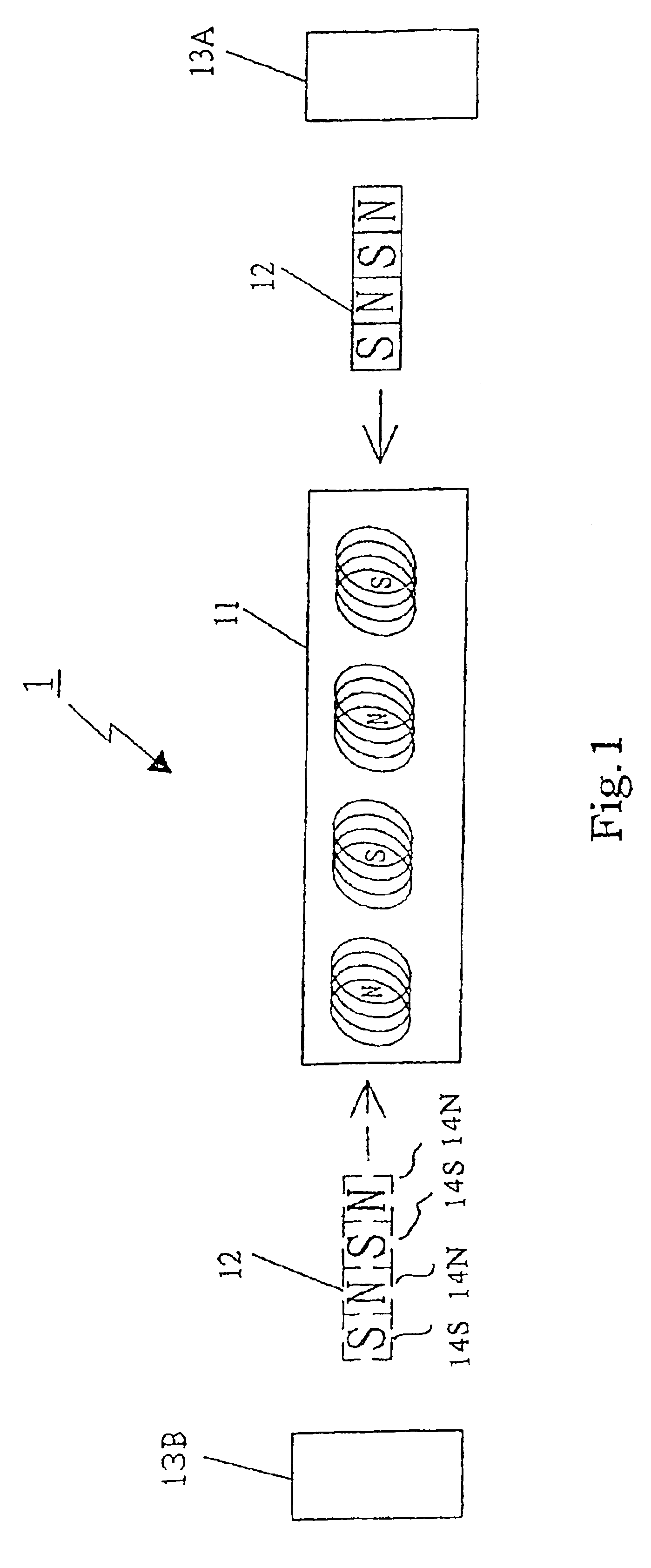
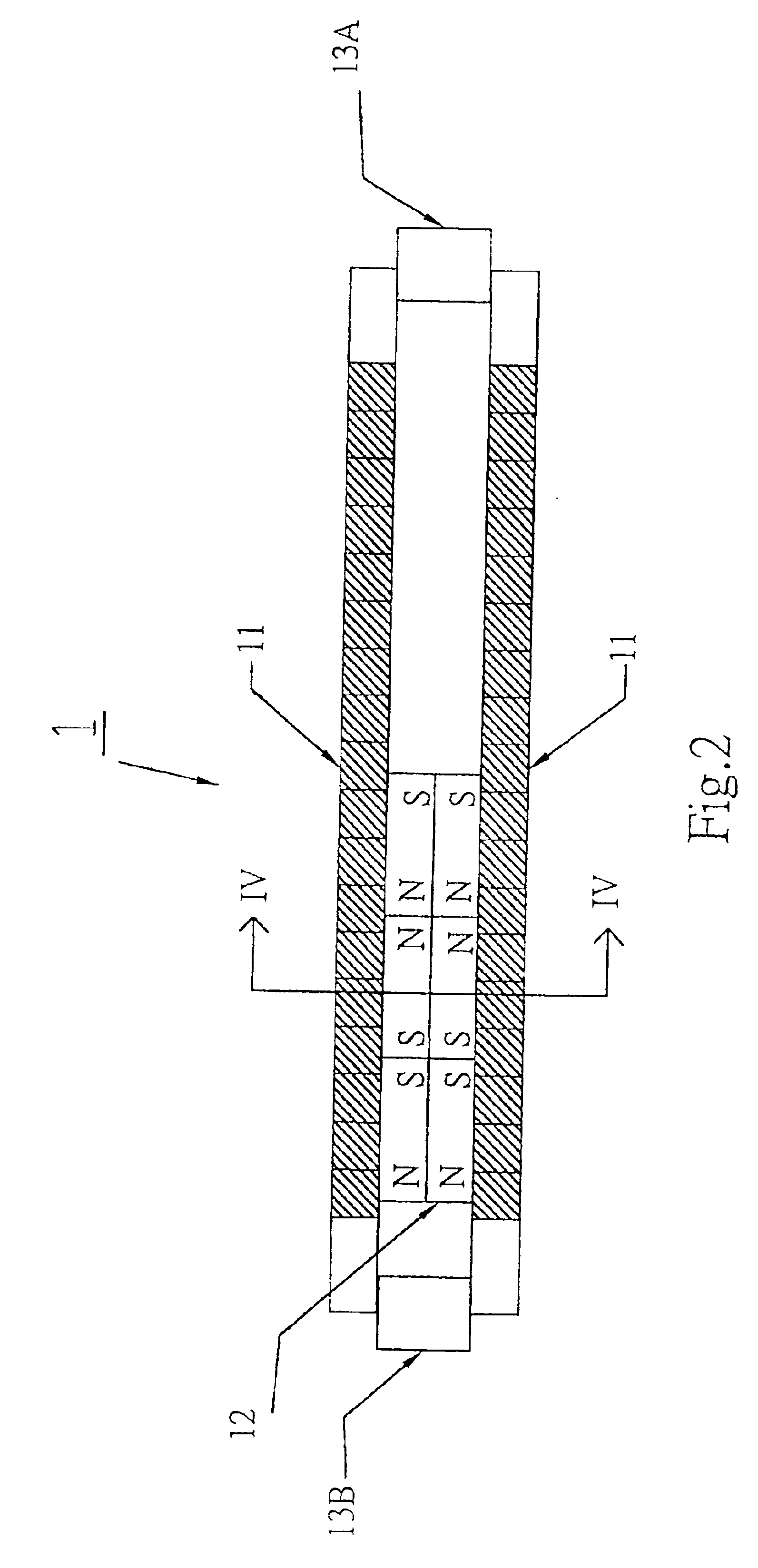
[0034]Referring to FIGS. 1 and 2, a linear electric generator 1 includes a plurality of stationary coil windings 11 and movably multiple pole armatures 12, each made up of serially connected dipole magnets and / or N-S alternating single pole structures 14S and 14N. FIGS. 2A and 2B show cross section views taken along line IV—IV of FIG. 2. The serially connected dipole magnets may optionally be constructed of pairs of dipole magnets, as illustrated in FIGS. 8, 9A and 9B and described below. However, the invention is not limited to multiple pairs of dipole magnets. Instead, the invention may be implemented by a single pair of pole structures.

[0035]In order to overcome the drag caused by interaction between the magnetic field of the armature 12 and windings 11, the linear electric generator 1 of the two preferred embodiments as shown in FIGS. 1 and 2 includes accelerating elements 13A and 13B at each end of the windings, in the path of the respective armatures 12 as shown in FIGS. 1 and...


PUM


Abstract

Linear electric generators include stationary windings and armature magnets arranged to reciprocate axially relative to the windings, or stationary magnet structures and movable windings arranged to reciprocate relative to the stationary magnet structures. The armature magnets or stationary magnet structures are in the form of multiple pole magnets made up of a plurality of individual pole structures, each pole structure including a pair of magnets joined to each other with facing poles of like polarity. In addition, the windings may be in the form of a double winding structure including at least one first clockwise winding and at least one second counterclockwise winding arranged in a multi-layered stacked arrangement.

Description

[0001]This application is a continuation-in-part of U.S. patent application Ser. No. 10 / 170,715, filed Jun. 14, 2002 now abandoned.BACKGROUND OF THE INVENTION[0002]1. Field of the Invention[0003]This invention relates to a linear electric generator of the type disclosed in parent U.S. patent application Ser. No. 10 / 170,715, and more particularly to a linear electric generator that includes one or both of the following:[0004]Armature magnets or multiple pole stationary magnet structures having a series of N-S alternating poles and constructed using a novel joining method that overcomes problems of high remanance and coercivity, and thereby increases flux density;[0005]Stationary or movable windings constructed using a novel winding method that results in maximum magnetic line cutting during linear motion.[0006]2. Description of Related Art[0007]In a linear electric generator, the magnetic elements and windings are in linearly reciprocal motion relative to each other. This linear reci...

Claims


Application Information

Patent Timeline
Patent Type & Authority Patents(United States)
IPC IPC(8): H02K39/00H02K35/02H02K35/00H02K1/00H02K3/00H02K33/00H02K41/00
CPCH01F7/021H02K35/00H02K35/02H02K39/00H01F7/0273
Inventor TU, YU-TAYEH, SHOW-JONG
Owner SUNYEN CO LTD
Why Eureka
Try Eureka