
Processor with dual-deadtime pulse width modulation generator

a generator and pulse width technology, applied in pulse manipulation, pulse technique, instruments, etc., can solve the problems of less than perfect switching characteristics of switching devices, and achieve the effect of improving the ability to deal

Active Publication Date: 2005-08-30
MICROCHIP TECH INC
View PDF218 Cites 28 Cited by
  • Summary
  • Abstract
  • Description
  • Claims
  • Application Information

AI Technical Summary

Benefits of technology

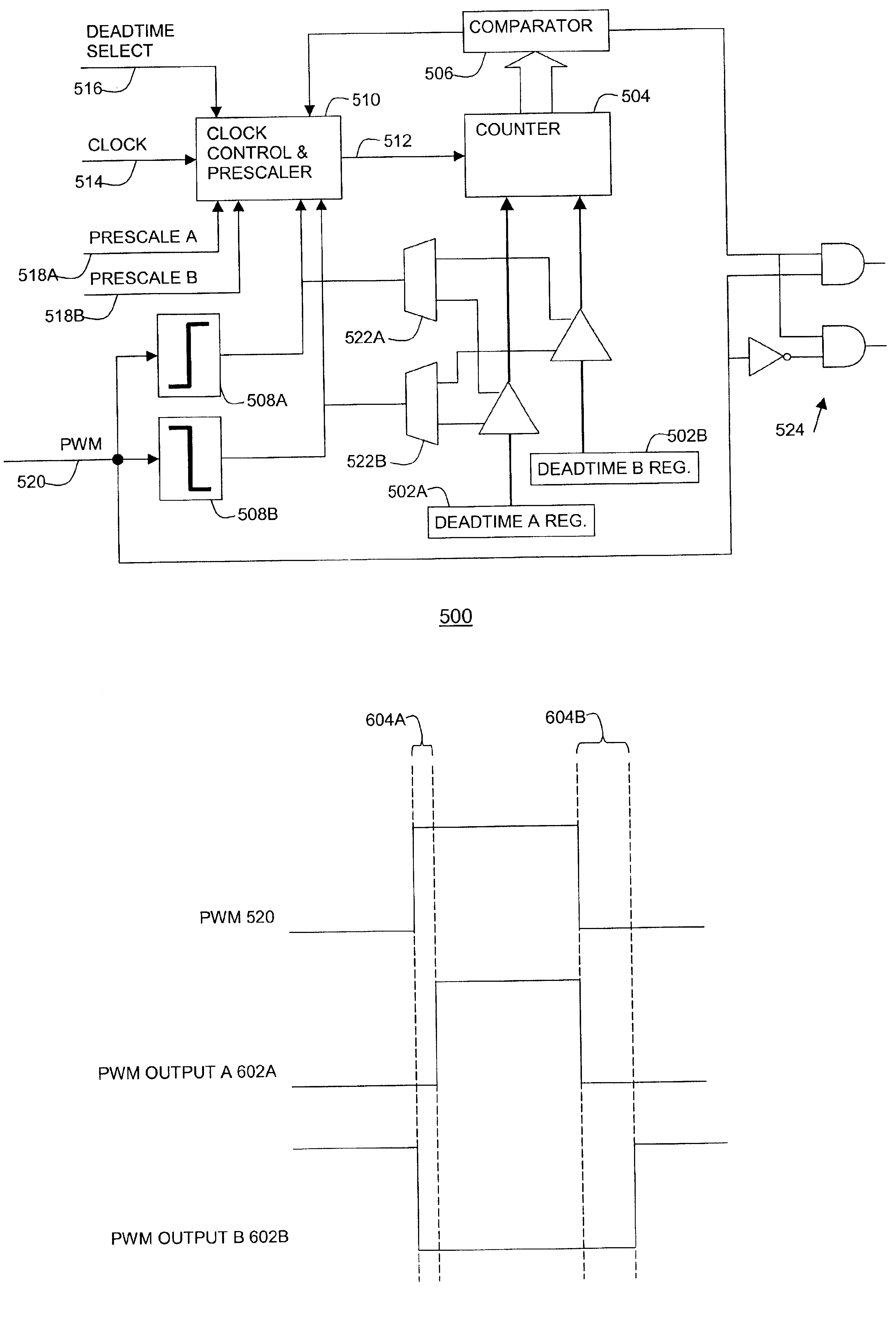
[0007]The present invention is a processor that has pulse width modulation generation circuitry that provides an improved ability to deal with the less than perfect switching characteristics of external switching devices that are connected to PWM hardware included in a processor. This is accomplished by providing complementary PWM output signals that have a deadtime delay, which is a delay between the inactivation of one signal and the activation of the complementary signal. The deadtime provides the capability to deal with the switching characteristics of external switching devices. Advantageously, the present invention provides dual deadtime capability. That is the delay between the inactivation of the first signal and the activation of the second signal may be different than the delay between the inactivation of the second signal and the activation of the first signal. This provides an improved capability to deal with non-symmetric switching characteristics of the external switching devices, and the circuitry to which they are connected.

Problems solved by technology

These switching devices have less than perfect switching characteristics, especially when connected to devices such as motors.
Problems arise with conventional PWM hardware, which has been included in current processors, in dealing with the less than perfect switching characteristics of connected switching devices.

Method used


Image

  • Processor with dual-deadtime pulse width modulation generator
  • Processor with dual-deadtime pulse width modulation generator
  • Processor with dual-deadtime pulse width modulation generator

Examples


Embodiment Construction

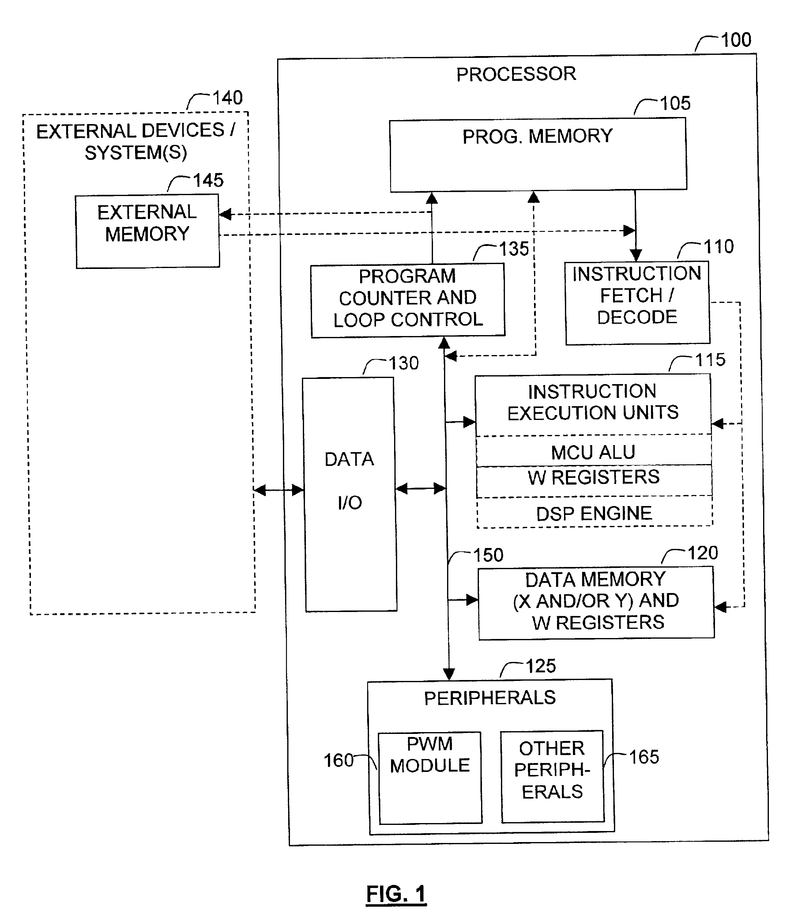
[0024]FIG. 1 depicts a functional block diagram of an embodiment of a processor chip within which the present invention may find application. Referring to FIG. 1, a processor 100 is coupled to external devices / systems 140. The processor 100 may be any type of processor including, for example, a digital signal processor (DSP), a microprocessor, a microcontroller, or combinations thereof. The external devices 140 may be any type of systems or devices including input / output devices such as keyboards, displays, speakers, microphones, memory, or other systems which may or may not include processors. Moreover, the processor 100 and the external devices 140 may together comprise a stand alone system.

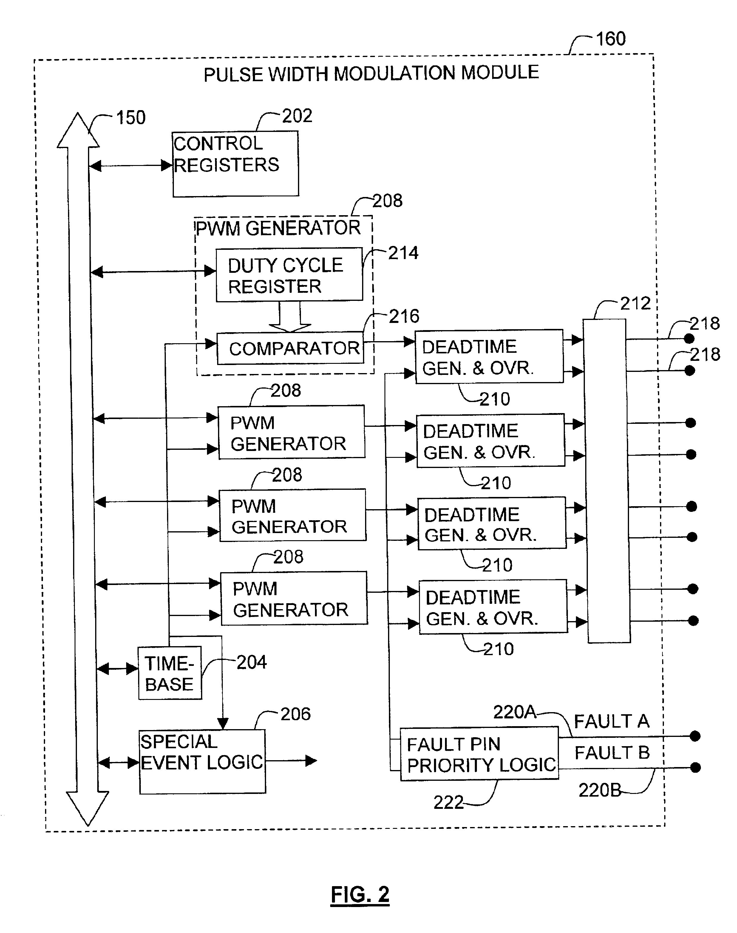
[0025]The processor 100 includes a program memory 105, an instruction fetch / decode unit 110, instruction execution units 115, data memory and registers 120, peripherals 125, data I / O 130, and a program counter and loop control unit 135. The bus 150, which may include one or more common buses, c...


PUM


Abstract

A processor that has pulse width modulation generation circuitry that provides an improved ability to deal with the less than perfect switching characteristics of external switching devices that are connected to PWM hardware included in a processor. Complementary PWM output signals have dual deadtime delay in which the delay between the inactivation of the first signal and the activation of the second signal may be different than the delay between the inactivation of the second signal and the activation of the first signal. This provides an improved capability to deal with non-symmetric switching characteristics of the external switching devices, and the circuitry to which they are connected. The dual deadtime pulse width modulation generator for a processor includes deadtime generation circuitry operable to generate a first pulse width modulated signal and a second pulse width modulated signal complementary to the first pulse width modulated signal, wherein there is a first delay between inactivation of the first pulse width modulated signal and activation of the second pulse width modulated signal, a second delay between inactivation of the second pulse width modulated signal and activation of the first pulse width modulated signal, and the first and second delays are not equal. The first delay and the second delay may be independently settable.

Description

FIELD OF THE INVENTION[0001]The present invention relates to a processor having a pulse width modulation (PWM) generator that generates deadtime delays in which the delay from the inactivation of a first signal to the activation of a second signal may be different than the delay from the inactivation of the second signal to the activation of the first signal.BACKGROUND OF THE INVENTION[0002]Processors, including microprocessors, digital signal processors and microcontrollers, operate by running software programs that are embodied in one or more series of program instructions stored in a memory. The processors run the software by fetching the program instructions from the series of program instructions, decoding the program instructions and executing them. In addition to program instructions, data is also stored in memory that is accessible by the processor. Generally, the program instructions process data by accessing data in memory, modifying the data and storing the modified data ...

Claims


Application Information

Patent Timeline
IPC IPC(8): H03K7/00H02M1/00H03K5/151H03K5/15H03K7/08H02M1/38
CPCH02M1/38H03K5/1515H03K7/08
Inventor BOWLING, STEPHEN A.
Owner MICROCHIP TECH INC
Learn More