Overdrive system and method of operating overdrive system

a technology of overdrive and overdrive system, which is applied in the direction of memory address/allocation/relocation, digital computers, instruments, etc., can solve the problems of low operating voltage of lcd devices, consuming very little electric power, and liquid crystal molecules having a relative slow response to electric fields, so as to reduce the overall complexity and production cost of display devices, the overall complexity of timing controllers is greatly reduced

Inactive Publication Date: 2005-08-30
INNOLUX CORP
View PDF7 Cites 19 Cited by
  • Summary
  • Abstract
  • Description
  • Claims
  • Application Information

AI Technical Summary

Benefits of technology

[0015]A second object of this invention is to provide an overdrive system and an operating method of the overdrive system that links a computer terminal to a display device. An overdrive look-up table required by the overdrive system is selectively installed inside either the computer terminal or the display terminal so that overall complexity of connectivity within the display device is reduced and hence production cost of the display device is lowered.
[0020]According to this invention, the frame buffer is installed inside the computer terminal and hence no addition memory is required inside the display terminal. Since additional setup for channeling the communication between the timing controller and the memory is unnecessary, design complexity of the timing controller is greatly reduced. In addition, the overdrive look-up table may be selectively installed inside either the computer terminal or the display terminal. Ultimately, overall complexity and production cost of the display device is further reduced.

Problems solved by technology

In general, an LCD device may operate at a low operating voltage and consume very little electric power.
However, liquid crystal molecules have a relative slow response to electric field.
Slow response to data voltage compared with a conventional cathode ray tube (CRT) display means that blurred images may form when motion pictures are displayed.
In other words, the transmission rate of image data to the LCD is so much faster than the response time of the LCD device that the liquid crystal molecules within the LCD device fail to follow well.
Although the aforementioned system is able to overdrive the LCD device, the display terminal 20 has a complicated structure and a high cost of production.
In addition, the overdrive look-up table 24 needs a ROM having a memory capacity of at least 64×64×3 bytes for holding overdrive display data values and hence incurs additional production cost.

Method used


Image

  • Overdrive system and method of operating overdrive system
  • Overdrive system and method of operating overdrive system
  • Overdrive system and method of operating overdrive system

Examples


first embodiment

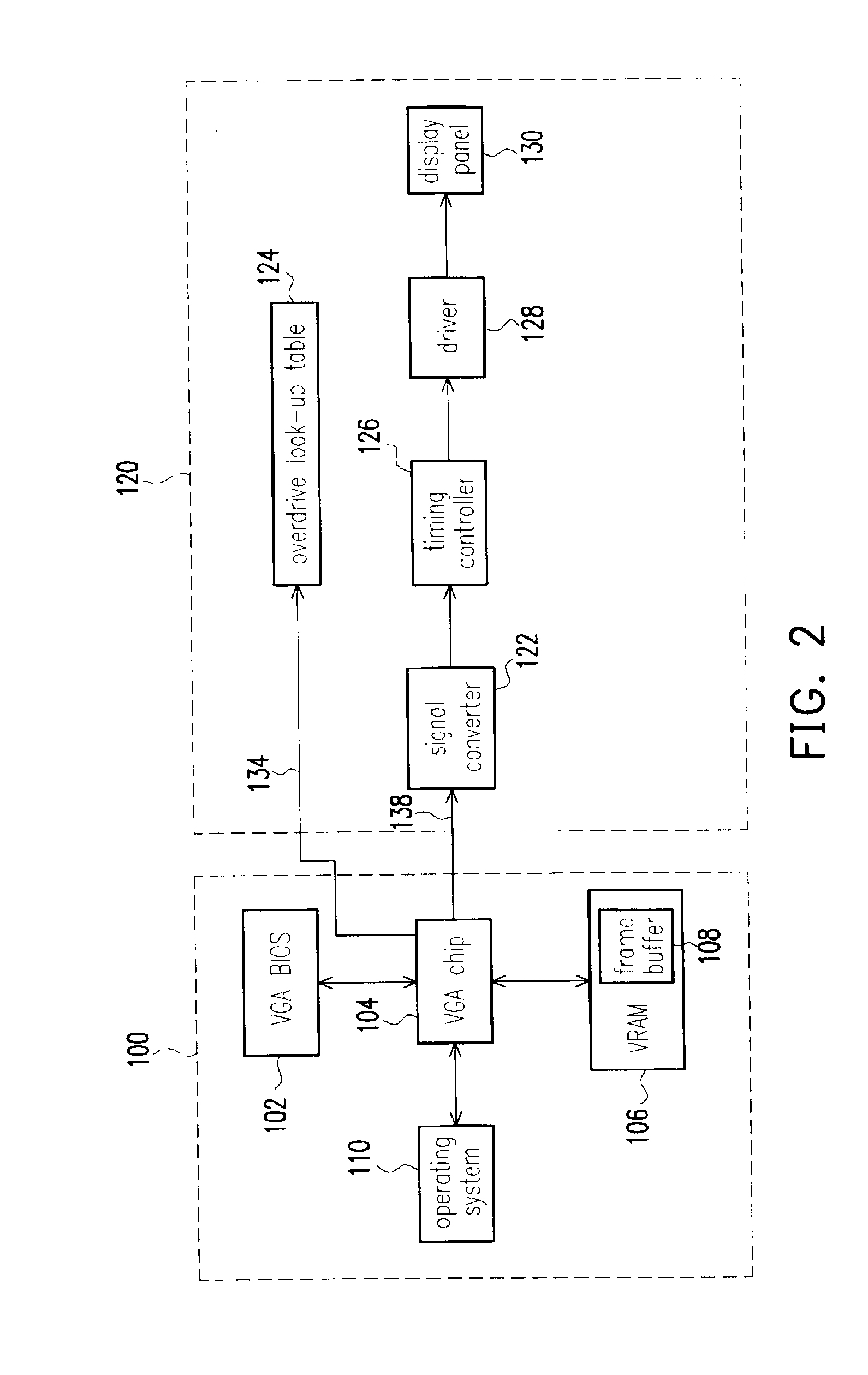
[0030]FIG. 2 is a block diagram showing an overdrive system for a display device according to this invention. As shown in FIG. 2, the overdrive system includes a computer terminal 100 and a display terminal 120. The display terminal 120 can be a liquid crystal display (LCD) and the computer terminal 100 is controlled by an operating system 110. The computer terminal 100 communicates with the display terminal 120 via a display interface. Image data are transmitted from the operating system 110 to the display terminal 120 through the display interface. Typically, the display interface has a plurality of sub-components including a VGA BIOS 102, a VGA chip 104 and a video RAM (VRAM) 106.

[0031]In this embodiment, a frame buffer 108 is embedded within the VRAM 106 of the computer terminal 100. Due to the rapid progress in display card technologies and the demands for multi-media techniques, most VRAM 106 has a relatively large memory capacity up to 64 MB or higher. Since the frame buffer ...

second embodiment

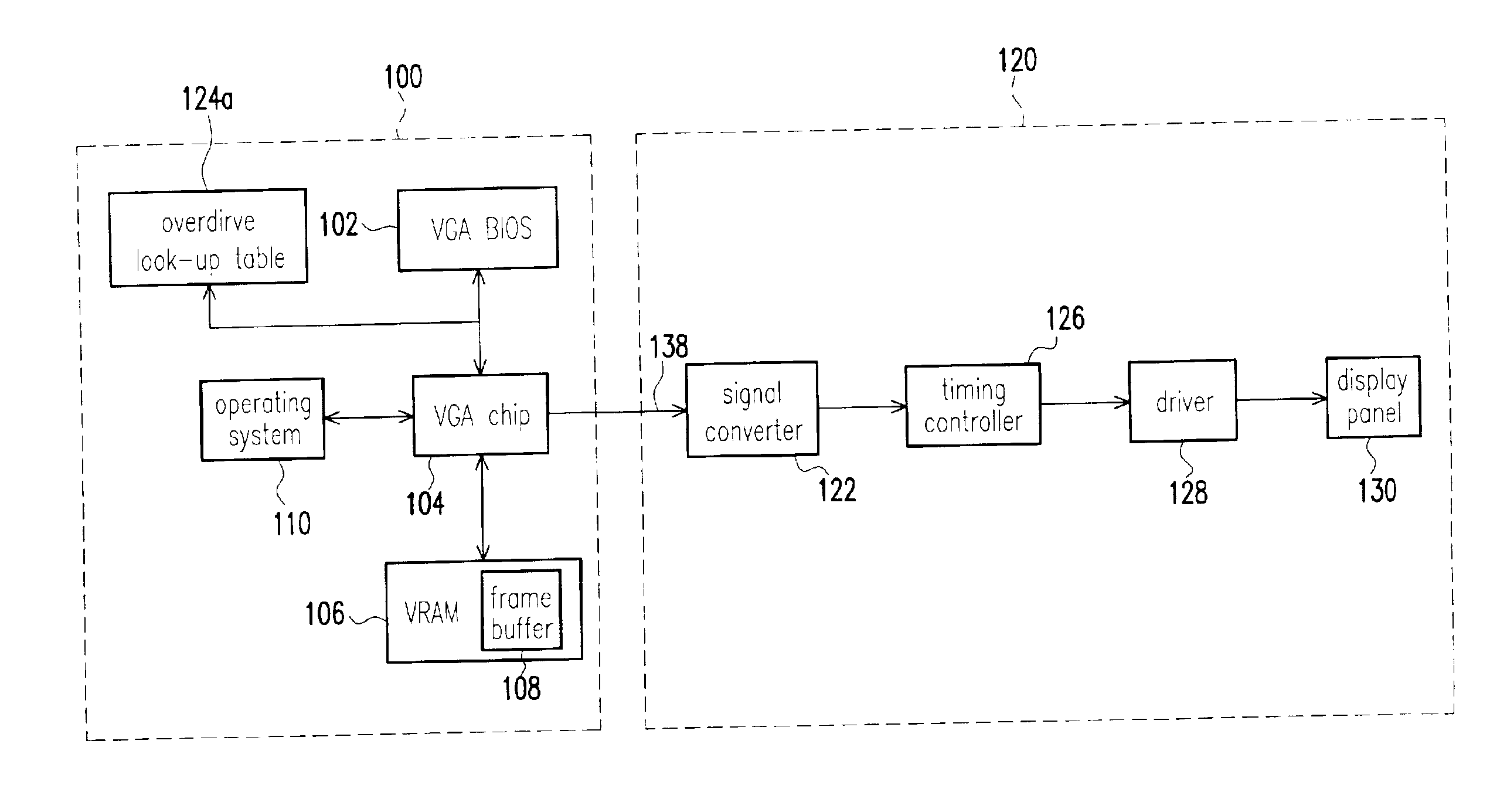
[0040]In the second embodiment, since both the overdrive look-up table 124a and the frame buffer 108 are moved from the display terminal 120 to the computer terminal 100, all overdrive functions are established within the computer terminal 100. Hence, the display terminal 120 can be simplified to reduce production cost.

[0041]Furthermore, since different display devices may require different overdrive display data, a set of display identification code may be introduced in the display interface so that the display interface may recognize the type of display device connected to the computer terminal. Once the type of display device connected to the computer terminal is identified, a corresponding overdrive look-up table may be retrieved to generate suitable overdrive display data for the device.

[0042]FIG. 4 is a block diagram showing an overdrive system for a display device according to a third embodiment of this invention what the third embodiment differs from the first and the second...


PUM


Abstract

An overdrive system for driving a display device. A host machine includes a display interface for connecting with the display device. The display interface includes a display chip and a video memory. The overdrive system includes a frame buffer for holding the display data of the previous frame. The frame buffer uses a portion of the video memory space. The overdrive system also includes an overdrive look-up table coupled to the display chip to provide a correspondence between the overdrive display data, the display data of the previous frame and the display data of the present frame. The display chip retrieves overdrive display data from the overdrive look-up table according to the display data of the previous frame obtained from the frame buffer and the display data of the present frame and transmits the overdrive display data to the display device so that an image is formed on the display panel.

Description

CROSS-REFERENCE TO RELATED APPLICATION[0001]This application claims the priority benefit of Taiwan application serial no. 90131023, filed Dec. 14, 2001.BACKGROUND OF THE INVENTION[0002]1. Field of Invention[0003]The present invention relates to an overdrive system and a method of operating the overdrive system of a display device. More particularly, the present invention relates to an overdrive system and a method of operating the overdrive system of a liquid crystal display (LCD) device.[0004]2. Description of Related Art[0005]A liquid crystal display (LCD) device applies electric field to drive liquid crystal molecules from an initial molecular alignment state to a different molecular alignment state. The change in molecular alignment brings about a change in optical property and visual appearance. In general, an LCD device may operate at a low operating voltage and consume very little electric power. Moreover, the LCD device can easily be driven by large scale integrated (LSI) ci...

Claims


Application Information

Patent Timeline
Patent Type & Authority Patents(United States)
IPC IPC(8): G09G3/36G09G5/36
CPCG09G3/3611G09G5/363G09G2320/0252G09G2340/16
Inventor LIN, WEN-TSUNGTSAI, YUNG-YULEE, HSIN-TA
Owner INNOLUX CORP
Why Eureka
Try Eureka