Compact digital timing recovery circuits, devices, systems and processes

Inactive Publication Date: 2005-08-30
CIRRONET
View PDF14 Cites 40 Cited by
  • Summary
  • Abstract
  • Description
  • Claims
  • Application Information

AI Technical Summary

Benefits of technology

[0005]The present invention is directed to compact and efficient circuits and processes for recovering the timing of bits from a received binary waveform in digital communications systems. Circuits and processes according to the present invention include a standard phase-locked loop incorporating an edge detector, phase d

Problems solved by technology

However, prior to the present invention, such clock reco

Method used


Image

  • Compact digital timing recovery circuits, devices, systems and processes
  • Compact digital timing recovery circuits, devices, systems and processes
  • Compact digital timing recovery circuits, devices, systems and processes

Examples


Embodiment Construction

[0025]While this invention is susceptible of embodiments in many different forms, there is shown in the drawings and will herein be described in detail preferred embodiments of the invention with the understanding that the present disclosure is to be considered as an exemplification of the principles of the invention and is not intended to limit the broad aspect of the invention to the embodiments illustrated.

[0026]The present invention includes various implementations of oversampling phase-locked loop based timing recovery circuits. One benefit of the present invention is that such circuits can be very compact, thereby using minimal resources within a digital logic chip or group of chips.

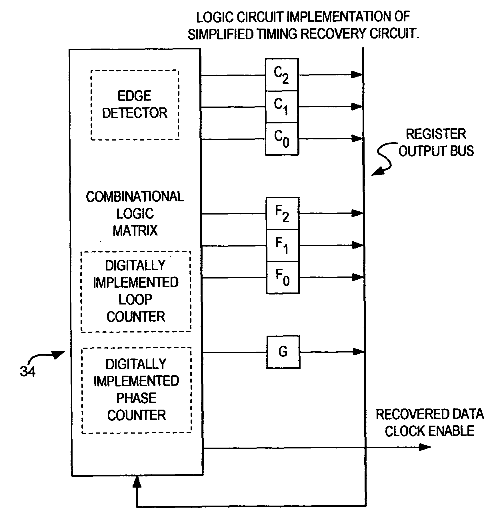
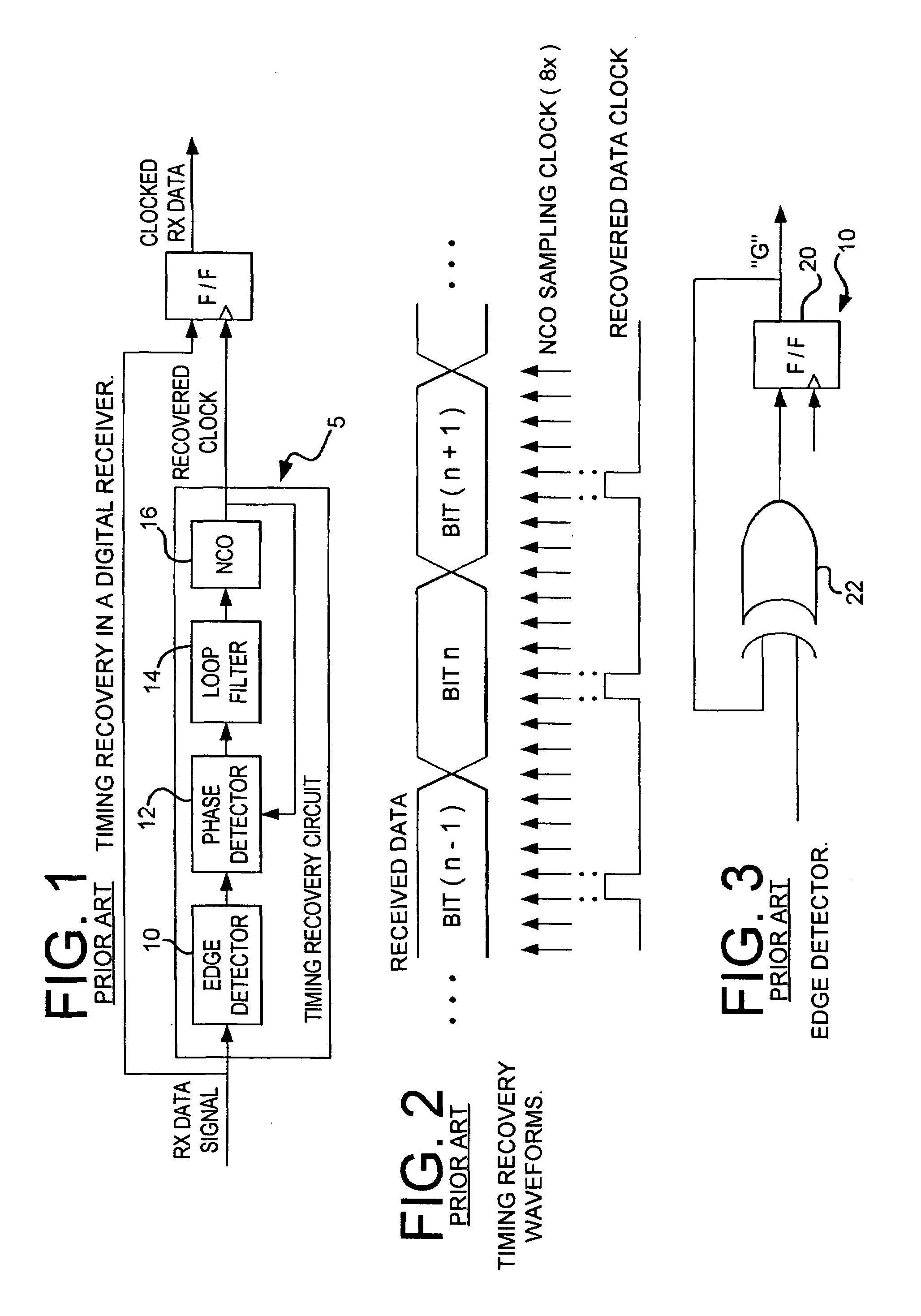
[0027]The organization of a timing recovery circuit 5 may be roughly broken down into several components. These include an edge detector 10, a phase counter and a loop filter 14. In the present invention, the phase detector 12 and NCO 16 functions that would be part of a normal PLL circuit are fold...


PUM


Abstract

A digitally implemented timing recovery circuit for recovering a clock signal from an input bit stream. The recovery circuit comprising an edge detector for detecting a transition from “0” to “1” or “1” to “0” in the input bit stream, a phase counter having a plurality of registers indicative of the phase counter transition state, and a loop counter having a plurality of registers indicative of the loop counter transition state. When the phase counter reaches a particular transition state, a recovered clock pulse is enabled. The phase counter is preferably non-linear to optimize the circuit.

Description

RELATED APPLICATIONS[0001]The present application claims priority from U.S. Provisional Patent Application No. 60 / 191,986, filed Mar. 24, 2000.TECHNICAL FIELD[0002]The present invention is generally directed to a digital timing recovery circuit, and more particularly, the invention is directed to a digital phase-locked tracking loop timing recovery circuit for use in a programmable logic device or integrated circuit.BACKGROUND OF THE INVENTION[0003]In digital communications networks, it is common practice to transmit a binary data stream without explicitly transmitting a corresponding clocking signal. In such instances, a clock signal must be recovered from the data stream itself. One method of achieving this is to detect edge transitions between data bits and input this information to a phase-locked tracking loop (PLL) which then generates the desired clock.[0004]Such a timing recovery circuit consists of an edge detector, a phase detector and a numerically-controlled oscillator (N...

Claims


Application Information

Patent Timeline
IPC IPC(8): H03D3/00H03D3/24H03L7/06H04L7/033
CPCH03L7/06H04L7/0331
Inventor RATZEL, DAVID G.
Owner CIRRONET
Why Eureka
Try Eureka