High-frequency module and radio device using the same

Inactive Publication Date: 2005-08-30
MURATA MFG CO LTD
View PDF18 Cites 27 Cited by
  • Summary
  • Abstract
  • Description
  • Claims
  • Application Information

AI Technical Summary

Benefits of technology

[0013]Accordingly, a high-frequency module according to various preferred embodiments of the present invention includes a high-pass filter or a notch filter as a high-frequency filter for attenuating spurious high-frequency signal, thus reducing the

Problems solved by technology

Such a typical RF circuit experiences problems with the insertion loss at the high-freq

Method used


Image

  • High-frequency module and radio device using the same
  • High-frequency module and radio device using the same
  • High-frequency module and radio device using the same

Examples


Example

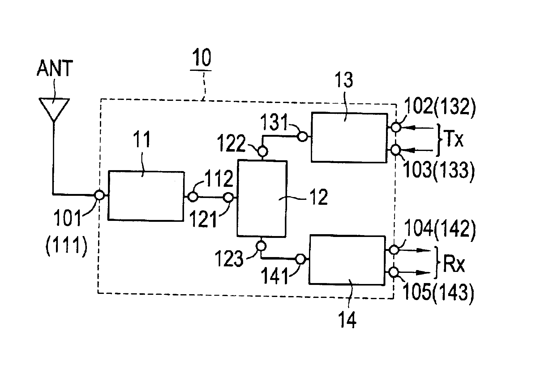
[0030]FIG. 1 shows a high-frequency module 10 according to a first preferred embodiment of the present invention. The high-frequency module 10 preferably includes first to fifth terminals 101 to 105, a high-pass filter 11, a high-frequency switch 12, a transmitter-side balun 13, and a receiver-side balun 14.

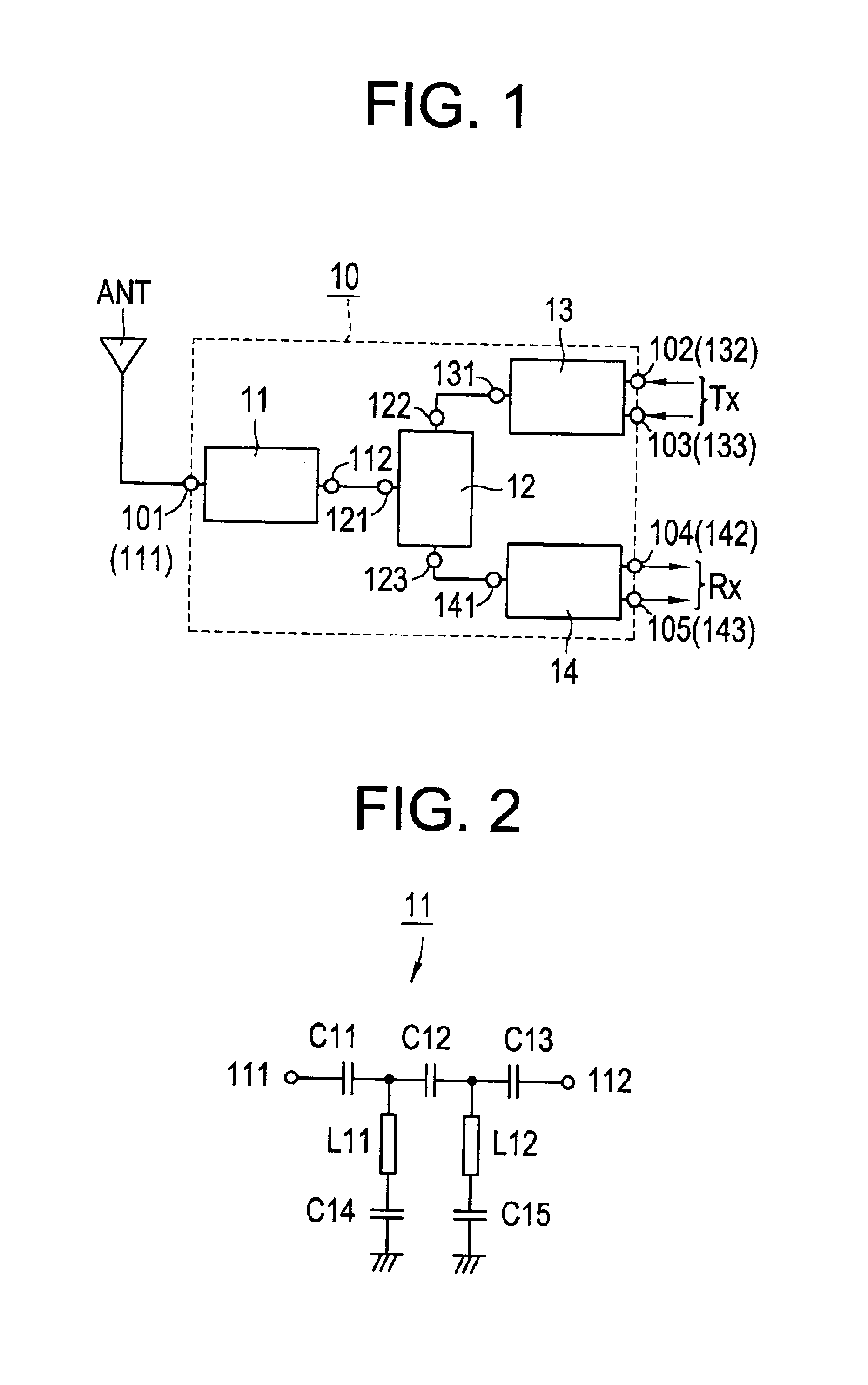
[0031]The high-pass filter 11 attenuates spurious high-frequency signal such as transmission and reception signals of other frequency band communication systems represented by GSM in the 900 MHz band, DCS in the 1.8 GHz band, and PCS in the 1.9 GHz band.

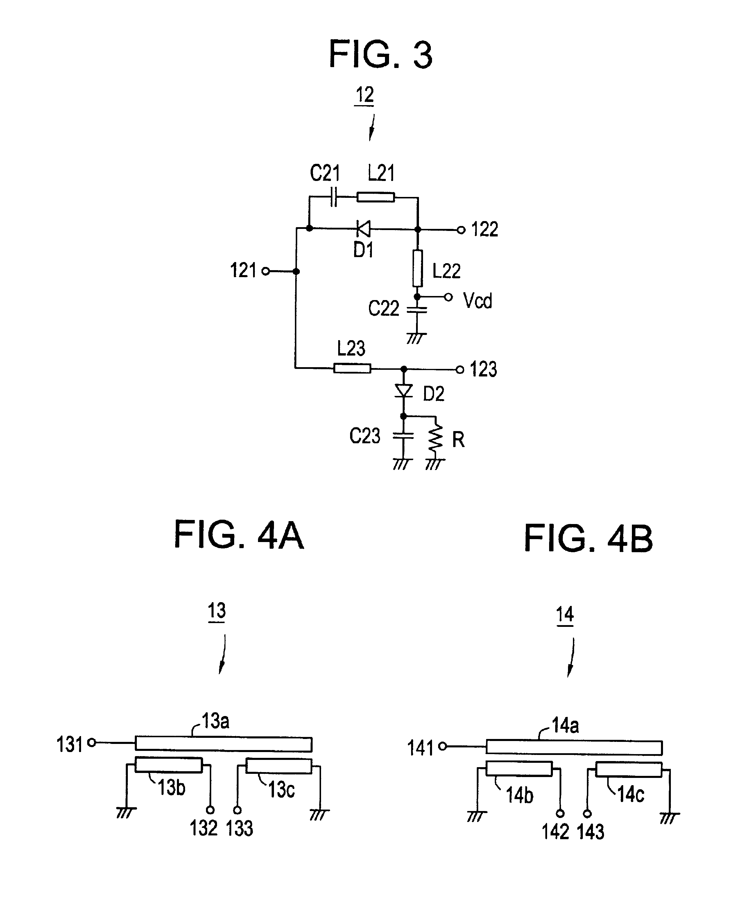
[0032]The high-frequency switch 12 switches a transmission signal and a reception signal, and attenuates the third harmonic of reception signal of the 2.4 GHz communication system of preferred embodiments of the present invention.

[0033]The transmitter-side balun 13 converts a balanced signal into an unbalanced signal. The receiver-side balun 14 converts an unbalanced signal into a balanced signal, and attenuates the second harmoni...


PUM


Abstract

A high-frequency module includes first to fifth terminals, a high-pass filter, a high-frequency switch, a transmitter-side balun, and a receiver-side balun. The high-pass filter is connected to the high-frequency switch, and the high-frequency switch is also connected to the transmitter-side balun and to the receiver-side balun. The first terminal is connected to an antenna, the second and third terminals are connected to a transmitter circuit, and the fourth and fifth terminals are connected to a receiver circuit.

Description

BACKGROUND OF THE INVENTION[0001]1. Field of the Invention[0002]The present invention generally relates to a high-frequency module and a radio device including the same, and more particularly, to a high-frequency module for use in a balanced transmitter / receiver system, and to a radio device including the same.[0003]2. Description of the Related Art[0004]In general, the 2.4 GHz band is an Industrial, Scientific and Medical (ISM) equipment frequency band, and is internationally allocated for industrial, scientific and medical use so as to prevent disturbances due to crosstalk or interference. The 2.4 GHz is utilized for wireless local area networks (LANs) because it ensures the bandwidth in which high-speed broadband communications of several megabits per second (Mbps) are possible, or because it has high availability and high radio-wave propagation at low cost.[0005]FIG. 13 is a block diagram showing a radio frequency (RF) circuit for Bluetooth, a wireless LAN protocol, which was su...

Claims


Application Information

Patent Timeline
IPC IPC(8): H01P1/15H01P1/10H01P1/213H05K3/46H01P5/10H03H7/075H03H7/42H04B1/3822H04B1/40
CPCH01P1/15
Inventor WATANABE, TAKAHIROYOSHIDA, NORIOITO, TOMONORI
Owner MURATA MFG CO LTD
Why Eureka
Try Eureka